Friday, August 24, 2018

Stepper Motor Control by Varying Clock Pulses

Stepper motor control circuit is a simple and low-cost circuit, mainly used in low power applications. The circuit is shown in figure, which consist 555 timers IC as stable multi-vibrator. The frequency is calculated by using below given relationship:

Frequency = 1/T = 1.45/(RA + 2RB)C Where RA = RB = R2 = R3 = 4.7 kilo-ohm and C = C2 = 100 µF.
Stepper Motor Control by Varying Clock Pulses


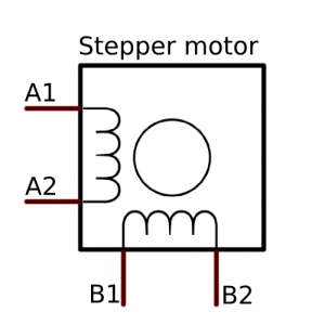
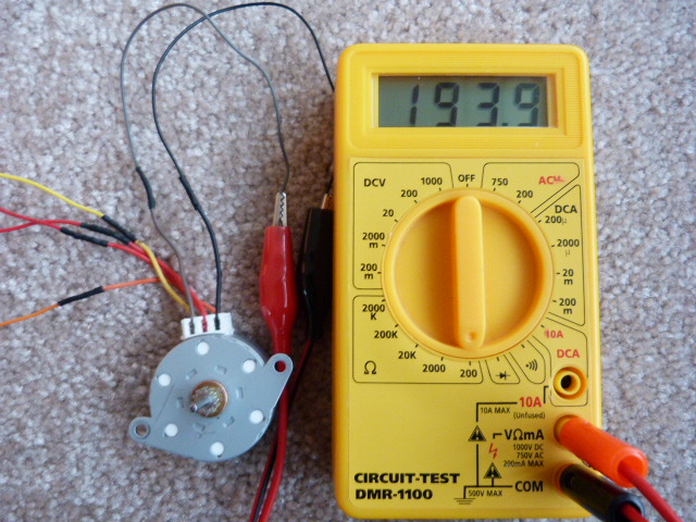
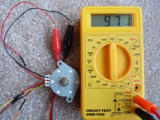
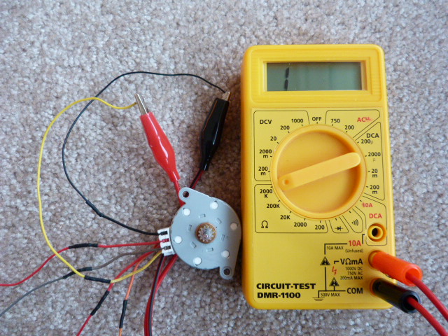
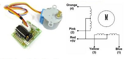
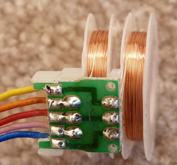
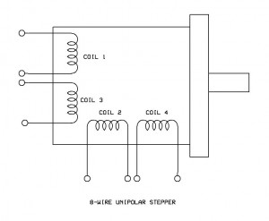
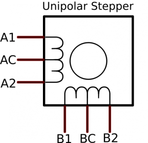
The output of timer is used as clock for two 7474 dual ‘D’ flip-flops (U4 and U3) configured as a ring counter. When power is initially switched on, only the first flip-flop is set (i.e. Q output at pin 5 of U3 will be at logic ‘1’) and the other three flip-flops are reset (i.e. output of Q is at logic 0). On receipt of a clock pulse, the logic ‘1’ output of the first flip-flop gets shifted to the second flip-flop (pin 9 of U3). Thus logic 1 output keeps shifting in a circular manner with every clock pulse. Q outputs of all the four flip-flops are amplified by Darling-ton transistor arrays inside ULN2003 (U2) and connected to the stepper motor windings orange ,brown, yellow, black to 16, 15 ,14, 13 of ULN2003 and the red to +ve supply.

The common point of the winding is connected to +12V DC CNC power supply, which is also connected to pin 9 of ULN2003. The color code used for the windings is may vary form make to make. When the power is switched on, the control signal connected to SET pin of the first flip-flop and CLR pins of the other three flip-flops goes active ‘low’ (because of the power-on-reset circuit formed by R1-C1 combination) to set the first flip-flop and reset the remaining three flip-flops. On reset, Q1 of IC3 goes ‘high’ while all other Q outputs go ‘low’. External reset can be activated by pressing the reset switch. By pressing the reset switch, you can stop the stepper motor. The motor again starts rotating in the same direction by releasing the reset switch.

Now you have got an idea about the types of super motors and its applications if you have any queries on this topic or on the electrical and electronic projects leave the comments below.

Friday, August 17, 2018

Stepper Motor Power Supply Choosing Guide

Some people may consider the stepper motor to be a bit more complex than a standard DC motor. This may be true to a degree, however stepper motors offer many more advantages compared to the DC motors. Some examples of these advantages include; easy control by computer, precise control of rotation, and high torque at low speeds.

350W 48V 7.3A 115/230V Switching Power Supply Stepper Motor CNC Router Kits

When constructing a robot, or other system that uses stepper motors, you’ll need to have a DC power supply that can run the stepper motor. Stepper motors will run better when the voltages is several times higher than their rated voltage.
The first thing you will need to do when choosing a stepper motor power supply is to add Stepper Motor Power Supply - Circuit Specialists up the voltage for your stepper motors. Determine the number of stepper motors in your system that have the same voltage requirements. Add their current ratings and this will help you determine which total current you will need. If you have four stepper motors and each needs ½ amp of current, your total needed current will be 2 amps.

Next you will need to examine the stepper motor specifications to determine the voltage rating. choose a power supply with a voltage at least double that voltage, and this will give you the voltage the power supply needs to run the stepper motors.

Now it is time to start browsing a power supply website to find a source for your stepper motors. The Circuit Specialists website offers a complete section dedicated to cnc stepper motor kit power supplies. This makes browsing for the proper power source quick and easy. The final step in this process is to begin on your project.

HOW DO STEPPER MOTORS USE CLOSED-LOOP TECHNOLOGY?


Saturday, August 11, 2018

How to identify four-wire stepper motor coil pairs with a multimeter

If your stepper motor has 4 wires, it is a bipolar stepper motor. Bipolar stepper motors have two windings, which are not connected to each other, wired internally like this:
Bipolar stepper motor
Since coils A and B on the diagram above are not connected, the resistance between leads A1 and B1, or between A1 and B2 will be infinite. The resistance between A1 and A2, or between B1 and B2 will be a definitely less than infinite (though more then zero), as they are part of the same winding. The physical location of the wires, or the colours may sometimes suggest the pairing, like in the photos below. Still, a simple check with a multimeter, set at its resistance measurement option can save you a lot of time troubleshooting your code and wiring.
Image 1: The black and yellow wire are not part of the same coil, as the multimeter shows high (infinite) resistance
Bipolar-Stepper-Motor-Wiring

Image 2: The orange and yellow wire are part of the same coil, as the multimeter shows resistance of approximately 18 Ohms.
Bipolar -Stepper-motor-Wiring

Now that we have determined which wires belong to each coil, how do we determine the proper stepper polarity? No way to do that with a multimeter, unfortunately…Connect the motor to your motor driver of choice. Connect power and run the code to spin the motor clockwise. If the motor spins in the expected direction, you have the correct polarity. If it spins in reverse, you need to switch the polarity of one of the two pairs (it does not matter which one).

How to identify six-wire stepper motor coil pairs with a multimeter

Stepper motors with six wires are unipolar and have one winding per phase (like the bipolar steppers) but with a center tap. The internal wiring of these motors looks like this:
unipolar-stepper-motor-wiring-labels
Looking at the diagram above, we can assume that the resistance between A1 and AC will be half of that between A1 and A2. This is because there is less wire between AC and A1 than between the two ends of the A coil, A1 and A2. The same applies to the resistance between BC and B1, or B2. Simillar to the case with the bipollar, 4-wire stepper motor, there is no connection (infinite resistance) between any of the wires from coil B and coil A. Time to put the theory to the test!
Image 3: The Black and Brown wires are obviously part of the same coil (resistance is approximately 194 Ohms)
Unipolar Stepper Motor Wiring Test
Image 4: The Black and the top Red wire (there are two red wires on this stepper) are also part of the same coil (resistance of approximately 97 Ohms).
Unipolar Stepper motor wiring test
The top Red must be the center tap of the coil with the Black and the Brown wires, as the resistance between the Red wire and the Black wire is half that of the resistance between the Black and the Brown wire. For a good measure you should also measure the resistance between the top Red and the Brown wire, to confirm it is also around 97 Ohms.
Image 5: The Yellow wire must not be part of the same coil as the Black, Brown and the top red wire. Multimeter shows no electrical connection between the Yellow and the black wires.
Unipolar Stepper Motor Wiring test
To make sure, I also double-checked the resistance between the bottom Red wire and the Yellow wire, as well as the resistance between the Yellow and Orange wires. Another measurement confirmed that the two Red wires are also not connected.
Final verdict: 
One coil is Black and brown wires, with the top Red wire as the center tap
The other coil is the Yellow and the Orange wires, with the bottom Red wire as a center tap.
If your motor has 5 wires test to see if one of the wires is not connected to the casing of the motor. If it is, then mark it and then proceed with the same test as with the four wire stepper motor. If no, then you are looking at a unipolar motor, where the two center tabs are connected. The cheap stepper motor (see tutorial) is an example of that.
28BYJ-48-Stepper-Motor-Coils
28BYJ-48-Unipollar-Stepper-Wiring

You can still use the resistance test to determine the center tap, but the resistance between the other 4 wires will be the same, due to the common center tap. Some trial and error, or good documentation will be useful here.
If your motor has 8 wires, the internal wiring should look like this.
8-wire-stepper-motor-coils
I never had on one of these type of steppers yet, so can’t speak from experience here, but using the multimeter and testing the wires in pair, should give you the pairs (eventually). You will need to do some extra work to determine which pairs are on the same coil. Likely this will require some trial and error, using your stepper motor driver.

Friday, August 3, 2018

Ideal application areas for closed loop stepper motors

The closed-loop method is also referred to as a sinusoidal commutation via an encoder with a field-oriented control. The heart of closed-loop technology is power-adjusted current control and feedback of control signals. Through the encoder, the rotor position is recorded and sinusoidal phase currents are generated in the motor coils. Vector control of the magnetic field ensures that the magnetic field of the stator is always perpendicular to that of the rotor and that the field strength corresponds precisely to the required torque. The current level thus controlled in the windings provides a uniform motor force and results in an especially smooth-running hybrid step motor that can be precisely regulated.

Ideal application areas for closed loop stepper motors


Closed loop stepper motors are an alternative when the application requires:
High torque at speeds up to 500rpm and a compact, economical solution without a gearbox,
Rapid commissioning without expensive tuning,
A load to be held in position while at a standstill,
Avoidance of transient and free oscillation behavior (hunting), which is typical of servo motors and occurs especially on variable loads and pulsation, leading to intolerable step errors. On sudden load changes, servo motors miss their positions and must be corrected.

Ideal application areas for best closed loop stepper motors:
Multiple axis applications (serial, Ethernet, EtherCAT, CANopen)
Positioning tasks with load changes
Winding applications
Belt drives (start/stop, positioning)
Dosing pumps, filler systems
Semi-conductor mounting
Wafer production
Textile machines/industrial sewing machines
Robotics
Testing and inspection systems
Applications that require quiet operation, short settling times and precision positioning.

WHAT ARE LINEAR STEPPER MOTORS?

Thursday, July 19, 2018

Typical Applications of 14 Stepper Motor

NEMA 14 Frame Size(35 x 35mm)
1.8° Step Angle
High Torque - Up to 56.6 oz-in
High Step Accuracy and Resolution
Low Vibration and Noise
CE Certified and RoHS
Can be Customized for
-Winding Current
-Shaft Options
-Cables and Connectors
Typical Applications of 14 Stepper Motor: Inject printers, Analytical and Medical Instruments, High Speed Dome Camera, Textile Equipment, Precision Telescope Positioning Systems, Embroidery Machine and Robotics
cnc stepper motor/step motor/stepper motor/Stepper Motor

Typical Applications of 14 Stepper Motor


The 14HS13-0804S Stepper Motor was developed primarily for users who have a restricted installation depth available and where a stepper motor with a construction size of 28 mm Stepper Motor is too long and a construction size of 39 mm Stepper Motor is too big. With the highest possible torque the Nema 14 Stepper Motor for sale series offers a high resolution and is deployed with low-priced power drive for applications in the precision device construction. We have 8-Lead Stepper Motor that can be connected in all possible configurations: series, unipolar, or parallel, to allow the maximum flexibility for your application. We can also customize Nema 14 Stepper Motor's winding to perfectly match voltage, current, and maximum operating speed to meet your requirements.

Need help choosing the right Stepper Motor? Read this: Uni-polar vs Bi-polar or learn more about Stepper Motor Basics.

Friday, July 13, 2018

Operating Instructions of Linear Stepper

In order for the linear stepper motor to operate properly, it will need to be connected to a motion controller or indexer and a stepper motor driver (with power supply). See diagram 1 for operation flow.


Operating Instructions of Linear Stepper


Step 1. A program or motion profile will be written on a PC or laptop and downloaded to the motion controller/indexer. This program will contain parameters such as speed, acceleration, deceleration, desired move, etc…

Step 2. Based on the program parameters, the motion controller/indexer will command the needed number of steps in the desired direction in order to move the desired amount.

Step 3. The microstepping driver will take the step & direction input signals and move the motor using the drivers set current. The bus voltage of the microstepping driver determines the max motor speed.

Step 4. The stepper motor linear actuator will move the desired amount at the programmed speed and acceleration. )

Monday, July 9, 2018

Different ways of stepper motors going into linear actuators

Stepper motors that are traditional rotary motors couple to mechanical rotary-to-linear motion devices (often in the form of a threaded shaft that mates with traversing nut or carriage) to produce linear motion. In this actuator setup, the motor output shaft usually couples to the screw to turn it … and advance the nut (or carriage) and attached load. These are usually small designs that go into consumer products or small-stroke applications in industrial machines.

In contrast, true linear stepper motors—which this FAQ covers in more depth—function much like linear-motor types but leverage the same mode of operation as rotary stepper motors to produce linear motion. More specifically, traditional linear-stepper motors (using variable-reluctance operation) have a moving carriage called a forcer with a permanent magnet, laminated steel cores (which the manufacturer cuts into teeth) and coils around the laminated cores. This forcer engages a straight and stationary track called a platen. This linear-stepper part is mostly steel bar cores (which the manufacturer cuts into teeth and plates with nickel). For super-long strokes, installers can put multiple platens end-to-end and have the forcer ride on all of them.

Summary of linear stepper motors
Engineers most commonly use these linear actuators in larger installations; on axes that move heavier loads; and in high-end medical or material-handling applications such as pick-and-place machinery that require extremely high precision. Like rotary equivalents, linear stepper motors or precision linear actuator either use a variable reluctance (just described) or a hybrid mode of operation. A hybrid linear-stepper platen is like that of a variable-reluctance linear stepper. In contrast, the forcer has multiple permanent magnets, magnetic U-shaped cores (with coils around them) and a steel yoke.

True Linear Stepper Motor

Development issues of right angle planetary gearbox

1.Basic definition of right angle planetary gearbox A right angle planetary gearbox is a compact device that uses a planetary gear system t...