Sunday, September 3, 2023

How to achieve innovation in hybrid stepper motors?

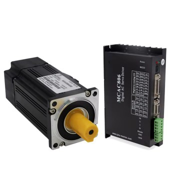
 Hybrid stepper motor is a type of motor that combines permanent magnet and reactive stepper motors. It has the advantages of high efficiency, low noise, high reliability, and has been widely used in many fields. So, in the face of the rapid development of the industry, how can companies in the hybrid stepper motor industry share a larger market share and occupy a larger market share? Here, the market breakthrough strategy of enterprises is very important. How to formulate a strategy and what kind of strategy to choose are related to the development of hybrid stepper motor companies in the next five or even ten years.


(1) Transform business philosophy

A successful business model for the hybrid stepper motor industry requires a clear positioning and approach. The market positioning must be accurate, and one should calmly analyze one's strengths and weaknesses, opportunities and threats, with clear development ideas and mature strategic tactics. Before the market matures, it is necessary to take the initiative, quickly change business ideas, and seize the first opportunity. In terms of the transformation of business processes in the hybrid stepper motor industry, the business model should be flexible. Take the path of characteristic management, that is, differentiated management strategy. In order to maintain continuous innovation, there should be a clear difference in business compared to competitors, which is exactly what customers need. We should be accustomed to learning how to better meet the needs of end users while also meeting their different needs.

(2) Integrate technical services

Technology is the key to achieving innovation. In this regard, we need to make more efforts in technology and services to welcome the arrival of a new era in the hybrid stepper motor industry. In terms of technology and services, the first step is to establish a comprehensive information management system, including new product information, technical information, competitor information, customer information, market information, and to timely analyze, process, and communicate the collected information. It is very important to improve the process technology and application range of hybrid stepper motors. For example, some domestic enterprises have achieved tracking and positioning of items by combining high-speed sampling controllers with hybrid stepper motors. In the application of industrial robots, reducing the side effects caused by the weight of hybrid stepper motors is not only a technical challenge, but also a development direction.


(3) Enhance growth motivation

Effectively transform from 'selling products' to' selling services'. The differentiated operation of hybrid stepper motor enterprises can only achieve results in terms of services. We should fully recognize that products can create value and profits, while good service can improve customer satisfaction, loyalty, and reputation. To provide high-quality after-sales service, enterprises need to pay attention to providing multiple contact information, training professional after-sales service teams, providing a comprehensive after-sales service system, providing value-added services to customers, and actively responding to customer feedback.


(4) Pay attention to environmental protection

The future development of hybrid stepper motors will place greater emphasis on environmental protection and energy efficiency. With the continuous improvement of global environmental awareness, people are paying more and more attention to energy conservation and resource utilization. Innovating the technology of hybrid stepper motors, pursuing high performance while also paying attention to environmental protection, has become an important force in promoting environmental protection and sustainable development.


Thursday, August 17, 2023

The advantages and disadvantages of integrated stepper motors

The stepper motor driver and motor can be integrated into one unit, which is an integrated motor. The manufacturer provides various combinations of integrated stepper motor driver combinations, each with its own advantages and disadvantages.

 
stepper motor driver
 
 
The advantages of integrated stepper motors include easy placement, reduced wiring complexity, faster system setup and construction, and motor driver compatibility. In addition, an integrated unit integrating the control system is also provided.
 
Easy on-site layout may be the most significant advantage of integrated motors. They do not require wiring between the driver and motor, and can be easily placed in the appropriate location and connected to the controller. This means that settings can be made faster to transition the motion control system from design drawings to production time in a short period of time.
 
 
Meanwhile, reducing wiring complexity means that engineers do not have to worry about whether the input and output are correctly connected between the driver and motor. Unipolar or bipolar wiring is no longer an issue. Similarly, interference between cables is reduced, and communication is greatly enhanced.
 
integrated stepper motors
 
Integrated motors also mean good compatibility between the motor and driver. It can be used together for they are provided together by the manufacturer. It can reduce the workload during the torque speed curve, as these have already taken into account the drive. For example, there is no need to worry about whether the driver provides the correct type of signal or uses the correct voltage, as all of these have been resolved. If the integrated unit comes with controls, it may be simpler and can handle most control operations. Meanwhile, the merged units can now be connected to other units, which is particularly useful in the Internet of Things.
 
The main drawback of this setting is the lack of implementation flexibility and potential supplier chain, which leads to troubleshooting issues and equipment maintenance changes. Because the drive motor combination is a unit, it is usually only applicable to certain applications and not to other applications. In addition, if the driver needs to be replaced but the motor is functioning properly, the entire unit can only be replaced.

Friday, August 26, 2022

Step Motor Systems: The Benefits of Adding Encoders

Use Encoders to Enhance Step Motor System Performance

Because of their low cost, high resolution, precise positioning, minimal control electronics and low cost, step motors are popular in automation. Traditional step motors can be driven in an open loop system without the need to have sensors to send information back to a controller. However, open loop step motors pose challenges.


Complex projects such as quadcopters require enhanced position control. The stepper motors are designed to provide excellent precision and predictable performance. This is possible when both the gearbox ratio and step angle are known.

Stepper motors are now the preferred choice for many electronic devices.

Some engineers go one step further than the stepper motor's excellent visibility into velocity and position.

They have also added encoders in their motor systems to the stepper's open loop control.


The Motor Encoder: Closed Loop Control is essential

An Stepper Motor w/ Encoder can be attached to an electric motor. It can be attached to an electric motor shaft to provide closed-loop feedback signals.


This functionality may seem redundant at first. Is precision control not what the stepper does by itself? It seems that both yes and no. Recent research has demonstrated that even though it may seem unnecessary, the encoder can make a huge difference in the performance of a stepper motor.


Galil, a motion controller manufacturer, conducted side-by-side tests between closed and open loop stepper motors. The team found that an encoder can make a significant difference in performance metrics.


The closed loop system offers:

Significantly improved velocity smoothness

Reduction in overall consumption


Three-phase brushless motors with comparable torque outputs can produce higher torque at lower speeds than comparable three phase brushless servomotors.

Galil's researchers found that stepper motors could achieve "dramatic" performance improvements by integrating a positional-feedback device with a two phase brushless amplifier. Their website contains their testing methods and results.

These are exciting developments in the world of motion control. Engineers of all levels can make stepper motors more powerful and economically viable by using readily available encoder technology.


Which ENCODERS IS BEST?

Optic encoders are a well-established technology. They offer reliable and accurate performance with a wide range resolutions. However, they can be subject to degradation and loss due to oil, dust, and other contaminants. They work best in clean environments. Capacitive encoders use newer technology and offer similar benefits. They provide the same speed and position information as optical encoders. They are also immune to environmental contaminants.


Saturday, August 20, 2022

Tips on How to choose a CNC Spindle motor

It is important to choose the right spindle or milling head. A "toy" brush spindle with a plastic housing might be sufficient for use in plywood and soft plastics. It is not suitable for professional use, i.e. to make money. It is not suitable for professional use (CNC Spindle Motor). It can be completed in just a few hours with hard work, and it can take up to six months with economical work.


Professional spindles use ceramic bearings on brushless inductive spindles with tight engine compartments and absolutely with metal housings. There are many options for spindle revolutions, power and output.

The nominal spindle speed of the identification plate is 12.000, 15.000 and 18.000 respectively. However, this does not necessarily mean that the spindle spins with these revolutions. The inverter can control the revolutions, but it is important to keep in mind that spindle power is the torque multiplied with rotational speed. This means that while the spindle speeds can be reduced by half, the power also falls. Here is where we need to compromise.

There is no one spindle that works for all applications. The spindle speed limitation is caused by the higher spindle power and larger bearing diameters. A larger bearing diameter means that the ball's centrifugal force is greater, which causes more heat to be released. One way to decrease this effect is to use lighter ceramic balls. 40.000 rpm spindles can be made only in low power settings.

Materials such as aluminum and wood, composite materials and laminates require high speed. High speed is not recommended when machining steel, particularly stainless steel, thermoplastics, or drilling with HSS drill bit bits.

The primary criteria for power is the maximum milling cutter diameter and materials to be cut with them. The spindle can be used to machine aluminum, plastic, wood, or laminate up to 5mm. It has cutters that are up to 8mm in diameter, 12mm in diameter, 3.3kW spindle, 16mm in diameter, and 5.6kW spindle. We should choose a lower-rpm spindle for steel. This means cutters between 10mm and 3.3kW spindle, cutters between 12mm and 5.6kW spindle as well as cutters between 16mm to 7kW spindle and cutters between 20mm to 10kW spindle.(Spindle Motor Inverter)

You should always choose a stronger spindle if you plan to drill steel. For example, a 6mm drill with a 5.6kW spindle at 2000rpm can drill steel at 2000rpm. Because spindles have gears, it is impossible to compare their power with conventional milling machines. Another thing. These spindles can last up to 10 years.


Wednesday, January 22, 2020

Torque vs Speed Characteristics of Steping Motor

The Speed-Torque graph indicates the characteristic relationship between the speed and torque when the stepping motor is driven. The torque vs speed characteristics are the key to selecting the right motor and drive method for a specific application. These characteristics are dependent upon (change with) the motor, excitation mode and type of driver or drive method. On the graph, the horizontal axis is the speed at the motor’s output shaft while the vertical axis is the torque.

Torque vs Speed Characteristics of Steping Motor


1.Maximum Holding Torque

The holding torque is the maximum holding power (torque) the stepping motor has when power (rated current) is being supplied but the motor is not rotating (with consideration given to the permissible strength of the gear when applicable).

2.Pull-in Curve
The pull-in curve defines a area refered to as the start stop region. This is the maximum frequency at which the motor can start/stop instantaneously, with a load applied, without loss of synchronism.

3.Pullout Torque Curve
Pullout torque is the maximum torque that can be output at a given speed. When selecting a motor, be sure the required torque falls within this curve.

4.Maximum Starting Frequency
This is the maximum pulse speed at which the hybrid stepping motor can start or stop instantaneously (without an acceleration or deceleration time) when the frictional load and inertial load of the stepping motor are 0. Driving the motor at greater than this pulse speed requires gradual acceleration or deceleration. This frequency drops when thereis an inertial load on the motor.

5. Maximum Slew Rate

The maximum operating frequency of the motor with no load applied.

Source:https://www.oyostepper.com/article-1110-Torque-vs-Speed-Characteristics-of-Stepper-Motor.html

Saturday, January 4, 2020

A Simple guide to identify the stepper motor you have

You’ve got your stepper motor from Ebay, the manual is in Chinese and you don’t have a clue if the motor is unipolar or bipolar.

Summarizing quickly.
If 8 wires, it will probably be unipolar 8 wires stepper motor, 4 per coil.
If 6 wires, probably unipolar, 3 for one coil and another 3 for the other. This means each coil has its own ground.
If 5 wires, probably also unipolar. 2 for one coil, 2 for the other and a common ground for both coils.
If 4 wires, probably a bipolar 4 wires stepper motor, 2 cables per coil.
I’ve also found this video which can help you differentiate the motor type you’ve got:

A Simple guide to identify the stepper motor you have

Wiring the stepper motors.
This will be a guide to connect the most common stepper motors for 3D printers. They usually mount NEMA17 with 4 wires.

Quick version.
If the motor comes with coloured wires, the typical colours are Red/Blue/Green/Black
Issues: It is not guaranteed to be like this! Who knows where the motors come from, how are they wired, etc. I’ve known many people who were not able to make them work and at the end, they realized the problem was in the wiring.

Longer version
The most common drivers which the 3D printers and home machines use are bipolar. The most known drivers for bipolar motors are pololus a4988 and DRV8825.
The motor will have 4 wires. 2 per coil, therefore what we have to figure out is which ones are the coils.

Figure out the coils
If we are going to wire a stepper motor, we have to figure out which wires belong to which coil.
We can name them coil A and coil B, or coil 1 and coil 2.
Luckily, the drivers designers decided to use both systems (/ironic)
If you read the driver’s label, the DRV8825 specifies A2 A1 B1 B2 and the A4988 specifies 1B 1A 2A 2B.
Just read it several times, and make sure you understand it is exactly the same.

Size and NEMA standard of Stepper Motor You Should Consider

Tuesday, December 31, 2019

Deciding when to use a non-captive linear actuator

Non-captive types of lead screw driven linear motor actuators are different from the more common external versions in that they allow the lead screw to completely pass through the motor. This fundamental difference offers advantages for those that have limited space available or are looking to shrink the overall size of their design package.

With an external actuator, the object being moved is mounted to the nut, and the screw rotates providing the motion along the length of the screw.
By contrast, in a non-captive actuator, the payload or object being moved is attached to the motor, and has screw ends that are typically fixed. In most cases, this setup can allow for a shorter overall screw to be used. It is also ideal for adding the external linear guide bearings that are almost always required for non-captive applications. They provide stiffness and eliminate deflection that causes premature wear on the nut, screw, and internal motor bearings.

A less common situation is where the device or payload is attached to the end of the screw. This is only used for very light loads and requires external linear guidance for stiffness. It is an arrangement that also requires clearance for the screw to extend out the opposite side of the motor.

One feature common to all non-captives is that the nut driving the screw is internal to the motor. Traditionally, this nut has been a standard nut with no mechanism to account for the play between the external threads of the screw and the internal threads of the nut. If, in this scenario, an anti-backlash capability was needed, manufacturers might be able to provide a custom solution, but with significantly higher cost and extended lead times.

To avoid this problem, PBC Linear offers the choice of a standard nut or anti-backlash nut within their non-captive linear actuators. We have the only anti-backlash nut and lead screw assembly available off-the-shelf in a non-captive configuration. This unique combination offers the best positional performance available in a non-captive hybrid actuator by utilizing our patented Constant Force Technology (CFT), which provides greater than two-times the superior backlash compensation as tested against competitors.

This advantage means that the self-lubricating nut will provide lubricant-free, consistent performance and preload over its lifetime. In addition, screws are available either uncoated or with a proprietary PTFE coating. These screws come with standard lead accuracy of 0.003 inches per foot, which is three-times better than typical screws on the market.

Non-captive linear actuators from PBC Linear go beyond the simple definition of motor and lead screw. They excel because they have been designed from the inside out, providing superior performance in linear motion applications.

With an external actuator, the object being moved is mounted to the nut, and the screw rotates providing the motion along the length of the screw.

By contrast, in a non-captive actuator, the payload or object being moved is attached to the motor, and has screw ends that are typically fixed. In most cases, this setup can allow for a shorter overall screw to be used. It is also ideal for adding the external linear guide bearings that are almost always required for non-captive applications. They provide stiffness and eliminate deflection that causes premature wear on the nut, screw, and internal motor bearings.

A less common situation is where the device or payload is attached to the end of the screw. This is only used for very light loads and requires external linear guidance for stiffness. It is an arrangement that also requires clearance for the screw to extend out the opposite side of the motor.

One feature common to all non-captives is that the nut driving the screw is internal to the motor. Traditionally, this nut has been a standard nut with no mechanism to account for the play between the external threads of the screw and the internal threads of the nut. If, in this scenario, an anti-backlash capability was needed, manufacturers might be able to provide a custom solution, but with significantly higher cost and extended lead times.

To avoid this problem, PBC Linear offers the choice of a standard nut or anti-backlash nut within their non-captive linear actuators. We have the only anti-backlash nut and lead screw assembly available off-the-shelf in a non-captive configuration. This unique combination offers the best positional performance available in a non-captive hybrid actuator by utilizing our patented Constant Force Technology (CFT), which provides greater than two-times the superior backlash compensation as tested against competitors.

This advantage means that the self-lubricating nut will provide lubricant-free, consistent performance and preload over its lifetime. In addition, screws are available either uncoated or with a proprietary PTFE coating. These screws come with standard lead accuracy of 0.003 inches per foot, which is three-times better than typical screws on the market.

Non-captive linear motor actuators from PBC Linear go beyond the simple definition of motor and lead screw. They excel because they have been designed from the inside out, providing superior performance in linear motion applications.

Source:https://blog.oyostepper.com/2019/12/31/deciding-when-to-use-a-non-captive-linear-actuator/

How to achieve innovation in hybrid stepper motors?

 Hybrid stepper motor is a type of motor that combines permanent magnet and reactive stepper motors. It has the advantages of high efficienc...