Saturday, December 21, 2019

What are Brushless DC Motors Used For?

Brushless DC motors typically have an efficiency of 85-90%, while brushed motors are usually only 75-80% efficient. Brushes eventually wear out, sometimes causing dangerous sparking, limiting the lifespan of a brushed motor. Brushless DC motors are quiet, lighter and have much longer lifespans. Because computers control the electrical current, brushless DC motors can achieve much more precise motion control.


Because of all these advantages, brushless DC motors are often used in modern devices where low noise and low heat are required, especially in devices that run continuously. This may include washing machines, air conditioners and other consumer electronics. They may even be the main power source for service robots, which will require very careful control of force for safety reasons.

Brushless DC motors provide several distinct advantages over other types of electric motors, which is why they’ve made their way into so many household items and may be a major factor in the growth of service robots inside and outside of the industrial sector.

If you think your application could benefit from this technology, browse a list of brushless DC motor here:
https://www.oyostepper.com/article-1105-What-are-Brushless-DC-Motors-Used-For.html

https://forum.nutsvolts.com/viewtopic.php?f=45&t=18023
http://blogs.rediff.com/myloveou/2019/12/21/some-useful-tips-of-controlling-a-bldc-motor/

The Most Common Applications of Stepper Motors

The Advantages of Stepper Motors
Not every application will benefit from a stepper motor, but in the right environment stepper motors can be ideal. First, stepper motors have full torque at standstill, and the rotation angle of the motor is proportional to the input pulse. Essentially, stepper motors offer excellent speed control, precise positioning, and repeatability of movement.

Additionally, stepper motors hybrid are highly reliable since there are no contact brushes in the motor. This minimizes mechanical failure and maximizes the operation lifespan of the motor. These motors can be used in a wide range of environments, as many different rotational speeds can be achieved because the speed is proportional to the frequency of pulse inputs.

The Most Common Applications of Stepper Motors


Applications of Stepper Motors
Stepper motors are diverse in their uses, but some of the most common include:

3D printing equipment
Textile machines
Printing presses
Gaming machines
Medical imaging machinery
Small robotics
CNC milling machines
Welding equipment
While these applications are the most common, they’re a fraction of what stepper motors can be used for. Generally speaking, any application that requires highly accurate positioning, speed control, and low speed torque can benefit from the use of stepper motors.

While servo motors have their place in industry as well as numerous advantages of their own, stepper motors are an ideal solution in many applications.

Stepper motors such as (14hs10-0404s, 17hs19-1684s-pg5)are a robust motion control technology and can be found inside of many common machines and equipment.

Brush DC Motor VS Brushless DC Motor

Friday, December 13, 2019

The difference Bettween 0.9 and 1.8 degree Step Size

On my Prusa Mendel RepRap I have Wantai stepper motors. I get them off Ebay, straight from the factory. Like something out of Home Improvement, I went a little over the top and got steppers that are a tad overpowered for 3D printing. But, I love them, they barely break a sweat or heat up even after hours of printing.

Stepper motors are a little different from most electric motors. Rather than just spin, they have the ability to ‘step’ and perform fairly accurate partial rotations. These steps make it very easy to tell your stepper motor to rotate say only 7.2°. This is really important for 3D printing, as a big element of 3D printing is just about making lots of these small, precise movements.


The super power 1.8 degree stepper motors that I run on my RepRap can make 200 steps in a single rotation, this means the smallest rotation they can possible do is 1.8°. I found some other stepper motors that can do a massive 400 steps a rotation, and got me wondering. If I upgraded my stepper motors, will I notice much of an improvement in print accuracy and quality? So I fired off a question to the now defunct Makers Stackexchange. Soon after, the awesome Adam Davis replied with the following answer.

The Answer:
The tradeoff, mechanically, between the two resolutions is typically a small decrease in torque due to the way stepper motors are designed.  You can compensate with higher currents or larger motors if needed.  You also need to double the speed of your driver to maintain the same machine speed if you go with a finer resolution stepper.  Check out and compare the motor specifications to see this effect as you move from one resolution to another in the same size motor package.

Further, current electronics packages and firmware tend to be designed for lower resolution, faster machines.  As such there are reports that you can only go up to 1/8 microstepping on the higher resolution steppers.  If you have 1/8 on the high resolution stepper, and 1/16 on the low resolution stepper, you end up with nearly the same effective resolution.

At this point in time the practical answer to the “will I get better/faster prints from a 0.9 degree stepper motor” is no.  If one costs less than the other, you might choose based on price.  If you are experimenting with high resolution, slow printing and you are writing your own controller firmware, then you might gain some benefit from the 0.9 degree steppers.

http://www.dreevoo.com/forum_post.php?idt=12483

SELECTING THE RIGHT LINEAR ACTUATOR BUILT-IN TECHNOLOGY

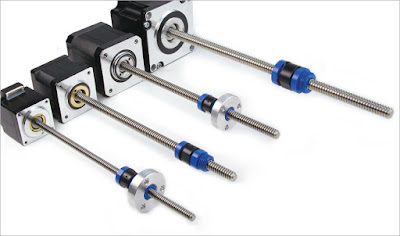
Generally, stepper motor linear actuators are available for standard stepper motor sizes (NEMA 8, NEMA 11, 14, 17, and 23 motor frame sizes), single or double stacked, with a variety of motor winding options and linear resolution options ranging from 0.063 to 7.5 μin of linear travel per step. Available offerings may differ in their ability to handle radial and moment loads, capability to integrate other devices, visibility of rotating parts, mounting options, and customization capability, so it is wise to consider your needs in these areas before purchasing one.

SELECTING THE RIGHT LINEAR ACTUATOR BUILT-IN TECHNOLOGY


Radial and moment load handling. Although most related applications involve axial loads, a properly fitted system should be able to achieve radial or moment loads of five to ten percent of the axial load. If your application requires radial and moment load handling, look for actuators with integrated bushings or other features that provide this ability for “side load.”

Integrating external devices. There is certainly a trend toward integrating multiple devices to improve control and reduce maintenance costs. It may, for example, be desirable to attach linear encoders to the back of the stepper motor. To keep this option open, avoid assemblies in which the screw extends out the back of the motor.

Mounting. If you are replacing existing motors, you can save yourself some trouble by purchasing a motor with NEMA-standard bolt-hole patterns. Hole positions can always be customized but starting with the NEMA standard will save you trouble on initial purchase and into the future.

Customization. In addition to bolt-hole pattern customization, customization options include end machining, wiring, cabling, and connectors.

If you have skilled resources in-house, building your own anti-rotational guidance for your integrated motorized lead screw actuator might have some short-term cost advantages; however, purchasing an integrated stepper motor linear actuator will get you into production faster and provide more accurate and reliable motion, while reducing longer-term maintenance and total cost of ownership.

Saturday, December 7, 2019

How to Connect stepper motors by using the internal and external drivers

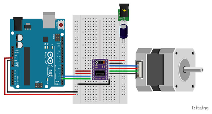
The Duet 2 WiFi, Ethernet and Maestro all have 5 on board stepper drivers.

To connect stepper motors to the internal drivers, refer to the wiring diagram at Duet 2 Wiring Diagrams or Duet 2 Maestro Wiring Diagram. The pinout of each stepper motor connector is the same as for other popular 3D printer electronics.

Note: it is highly recommended that the stepping motor casings be grounded, especially in belt-driven printers. Otherwise, motion of the belts causes static charge to build up, which eventually arcs over to the windings. If the motors are screwed to a metal frame, grounding the frame is sufficient.

Each stepper motor connector has four pins. You must connect the two wires for one phase of the stepper motor between the two pins at one end of the connector, and the wires for the other phase to the two pins at the other end.

Identifying the stepper motor phases
Here are two ways you can pair the stepper motor wires into phases:

Use a multimeter. There should be a few ohms resistance between two wires that belong to the same phase, and no continuity between wires that belong to different phases.
With the motor wires not connected, spin the spindle between your fingers. Short two of the wires together, then spin the spindle again. If it is much harder to spin than before, those two wires belong to the same phase. Otherwise, try again with a different pair of wires shorted together.

Block Image

Duet 2 (WiFi, Ethernet and Maaestro)
If you have two Z stepper motors, connect them to the ZA and ZB connectors. These connectors are wired in series, which is better than wiring them in parallel for most types of stepper motor used in 3D printers.

If you have only one Z stepper motor, plug it in to the ZA connector, and plug two jumpers into the ZB connector. Duet 2 boards are normally supplied with these jumpers already fitted.

Duet 0.6 and 0.8.5
If you have two Z stepper motors, then for the types of motors commonly used in RepRaps (i.e. with rated current in the 1.2 to 2.0A range), it is better to connect them in series than in parallel. Google "wiring stepper motors in series" for instructions on how to do this for example:

http://www.instructables.com/id/Wiring-Y...]

Using more than one motor on an axis with a separate driver for each motor
Use the M584 command (see http://reprap.org/wiki/G-code#M584:_Set_...) to specify which drivers are used for the axis concerned. You must be using RepRapFirmware 1.14 or later.

Using external drivers
See the using external drivers page for more details

If your motors are rated above about 2.8A and you are using the Duet 2 (Wifi or Ethernet), or above about 2A and you are using the Duet 2 Maestro, or obsolete Duet 0.6 or 0.8.5, or if they need higher voltage than the Duet can provide, then you need external stepper motor drivers. These generally have optically isolated step/dir/enable inputs. For example, stepper motor drivers rated at up to 5A using the TB6600 stepper driver chip are widely available on eBay.

If the drivers require no more than about 2mA @ 3V on the step, dir and enable inputs, then you can drive them directly from the expansion connector of the Duet. See the Duet 2 Wiring Diagrams for the expansion connector pinouts. Otherwise, you should use 3.3V to 5V level shifting ICs such as 74HCT04 to boost the signal level to 5V and drive them. You can use the Duet Expansion Breakout Board for this purpose.

To remap the X, Y or Z motors to external drivers in RepRapFirmware 1,14 or later, use the M584 command (see M584 Gcode). The Enable signals on the expansion connector are active low by default but you can change this using the M569 command (see M569 Gcode). You can also set a minimum step pulse width in the M569 command (try 1us or 2us when using external drivers), and configure the direction.


Checking connected stepper motors
Before conducting this step, temporarily alow axis movement without homing by navigating to the G Code console and entering: M564 S0 H0.
Block Image

Navigate back to the Machine Control page. At this time, we will check the operation of our stepper motors.

Block Image
Move each stepper motor, individually, 1 mm in each direction.

Note that a stepper can't be moved before homing, unless the M564 command is used to override this safety default.

https://interestpin.com/user/pin/3842/shakuken3212
http://www.bigbubblers.com/forum/viewtopic.php?p=11567

What Factors Should Take into Considertation When Choosing a Gearbox Stepper Motor

Service factor: The starting point for most gearbox stepper motor supplier is to define a service factor. This adjusts for such concerns as type of input, hours of use per day, and any shock or vibration associated with the application. An application with an irregular shock (a grinding application, for example) needs a higher service factor than one that’s uniformly loaded. Likewise, a gearbox that runs intermittently needs a lower factor than one used 24 hours a day.

How to Choose a Gearbox Stepper Motor
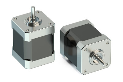
17hs19-1684s-pg5
17hs15-1684s-pg5


Class of service: Once the engineer determines the service factor, the next step is to define a class of service. A gearbox paired to a plain ac motor driving an evenly loaded, constant-speed conveyor 20 hours per day may have a service class 2, for example.

Overhung load: After the designer picks a size, the gearbox manufacturer’s catalog or website lists values for the maximum overhung load that is permissible for that sized unit. Tip: If the load in an application exceeds the allowed value, increase the gearbox size to withstand the overhung load.

Mounting: At this point, the designer or manufacturer has defined the gearbox size and capability. So, the next step is to pick the mounting. Common mounting configurations abound, and gearbox manufacturers offer myriad options for each unit size. A flanged input with hollow bore for a C-frame motor combined with an output shaft projecting to the left may be the most common mounting, but there are many other choices. Options such as mounting feet for either above or below the body of the gearbox, hollow outputs, and input and output configuration are all possible. All gearbox manufacturers list their mounting options as well as dimensional information in catalogs and websites.

Lubricant, seals and motor integration: Once unit size and configuration is complete, a few specifications remain. Most manufacturers can ship gearboxes filled with lubrication. However, most default to shipping units empty to let users fill them on site. For applications where there is a vertical shaft down, some manufacturers recommend a second set of seals. Finally, because many gearboxes eventually mount to a C-frame motor, many manufacturers also offer to integrate a motor onto the gearbox and ship the assembly as a single unit.

One final tip: Once the gearmotor has been chosen and installed in the application, perform several test runs in sample environments that replicate typical operating scenarios. If the design exhibits unusually high heat, noise or stress, repeat the gear-selection process or contact the manufacturer.

Wednesday, December 4, 2019

How to Select a stepping motor and power supply voltage

The choice of a stepper motor and power supply voltage is entirely application dependent. Ideally the motor should deliver sufficient at the highest speed the application requires and no more.
Featured Image
Any torque capability in excess of what the application requires comes at the high cost of unnecessary motor heating. Excess torque capability beyond a reasonable safety margin will never be used but will exact the penalty of an oversized power supply, drive stress and motor temperature.
Learn to distinguish the difference between torque and power; high initial torque at low speed does not mean efficient motor utilization. Usually, power is the more important measure of a motor’s suitability to an application. To determine this, you must bias the motor’s operating point through power transmission gearing to operate the motor at its maximum power; normally just past its corner frequency.
The maximum shaft power sustainable with a drive running at 80VDC and 7A is around 250W, or one third of a horsepower. This is primarily achieved with double or triple stacked NEMA 34 motors.
NEMA 23 motors are physically too small to dissipate the resultant hear and NEMA 42 motors are too big to be properly impedance matched; if their current is less than a 7A drive’s limit then the voltage will generally be above the maximum voltage of 80VDC and vice versa.
The detent torque on a NEMA 42 motor is significantly higher than in smaller motors and is always a loss that must be subtracted from the potential available power output of the motor. In other words, the output power of a NEMA 42 stepper motor drops more rapidly with speed than smaller motors. A NEMA 42 motor should be used only if high torque is required at low speed and it is not practical to gear down a smaller motor.
An efficient motor, defined as the smallest motor sufficient to meet the demands of the application, will run hot. Think of the motor as having fixed power conversion efficiency: Some percentage of the input power will be converted to heat and the rest will be converted to mechanical power. To get the maximum performance from the motor, the waste heat must be just under what the motor can tolerate. Usually this motor will be biased to operate just past the corner speed as well.
The place to start is to determine the load torque in oz/in, including the torque necessary to accelerate the load. The next step is to come up with the maximum speed the application has to operate at in full steps per second using the formula below. RPI is the revolutions per inch after the motor turns through the transmission, RPS is revolutions per second and PPS is the number of pulses per second from your step pulse source.
(DESIRED IPM * RPI) / 60 = RPS
RPS * 200 = PPS
Multiply the PPS value by the number of oz/in determined previously and divide the total by 4506. The answer will be how many watts mechanical are required from the motor to meet the load from the application. When picking a motor, choose one with 40% more than the calculated power. Below is an example of the equation completed for a load requiring 450 oz/in with a 3 TPI leadscrew and a desired IPM of 300.
(300 * 3) / 60 = 15
15 * 200 = 3000
(3000 * 450) / 4506 = 299 OZ/IN
299 * 1.4 = 419 OZ/IN
As you can see, you will want to use a motor with a rating of 419 oz/in for this application.

How to enhance the control capability of linear guide rails?

1.Brief of linear guide rail A linear guide rail is a mechanical component used in linear motion systems to guide and support a moving carr...