Tuesday, August 19, 2025

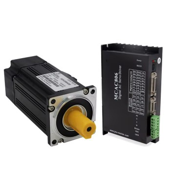
What are the precautions for using closed-loop stepper motors?

1.What is a closed loop stepper motor?

A closed-loop stepper motor is a type of stepper motor that incorporates a feedback mechanism, typically an encoder, to continuously monitor the motor's position and correct for any deviations from the commanded position. Unlike traditional open-loop stepper motors that operate without feedback, closed-loop systems provide enhanced accuracy, improved torque performance, and greater reliability, especially in applications with varying loads. 

2.Working principle of closed loop stepper motor

1.Command Input:The system controller sends a command (e.g., desired position, speed, or torque) to the motor driver. 

2.Initial Movement:The driver sends electrical pulses to the motor, causing it to rotate and move towards the target position. 

3.Feedback and Correction:The encoder monitors the motor's actual position and sends this information back to the driver. If the motor's position lags behind or deviates from the commanded position, the driver adjusts the current and pulse sequence to compensate and bring the motor back on track. 

4.Error Detection and Alarm:In cases of extreme overload or obstruction, the motor might not be able to move as commanded. The encoder will detect this error, and the driver can send an alarm signal back to the controller, potentially halting the system to prevent damage.     

3.Performance advantages of closed loop stepper motor

1.Enhanced Accuracy and Precision:Closed-loop systems utilize encoders to continuously monitor the motor's position and provide feedback to the controller.This feedback mechanism allows the system to detect and correct any deviations from the commanded position, resulting in improved accuracy and precision, especially in applications requiring high-precision motion control.

2.Improved Reliability and Step Loss Prevention:Open-loop stepper motors are susceptible to step loss, especially under heavy loads or at high speeds, which can disrupt operations and lead to errors.Closed-loop systems eliminate step loss by constantly monitoring the motor's position and adjusting the control signals to compensate for any deviations.This ensures that the motor always reaches its intended position, even under varying loads or during dynamic movements. 

3.Increased Efficiency:Closed-loop stepper motors can optimize power consumption by dynamically adjusting the current supplied to the motor based on the load and speed requirements. This dynamic adjustment reduces energy waste and heat generation compared to open-loop systems that operate at a fixed power level. The improved efficiency translates to lower energy costs and a more stable operating environment. 

4.Higher Torque at Low Speeds and Faster Positioning:Closed-loop systems can provide higher torque at low speeds compared to open-loop systems, enabling the use of smaller motors in certain applications.They also offer faster and more accurate positioning due to the real-time feedback mechanism. 

5.Diverse Applications:Closed-loop stepper motors are well-suited for a wide range of applications, includingRobotics,Semiconductor manufacturing,Medical devices,3D printing,CNC machines.     

4.Precautions for using closed-loop stepper motors

1.Encoder and Control System:Ensure the encoder is correctly wired and that the encoder resolution settings match those of the controller to avoid position errors and inaccurate feedback. Verify the controller is compatible with the closed-loop stepper motor and encoder system. Be aware that microstepping settings primarily affect the smoothness of rotation, not the overall positioning accuracy. 

2.Heat Dissipation and Environment:Closed-loop stepper motors, like other motors, have temperature limitations. Ensure the motor and driver operate within the specified temperature range (e.g., typically below 80°C for integrated closed-loop stepper motors). Proper cooling is crucial. Consider using upright installation to maximize air convection and, if needed, install fans near the driver to dissipate heat. Avoid dusty, oily, corrosive, or excessively humid environments. Also, protect the motor from vibration and strong magnetic fields. 

3.Emergency Stop and Fault Handling:Implement an external emergency stop circuit to quickly cut power and halt operation in case of an abnormality. Be aware that closed-loop systems can enter an alarm state if position errors exceed the threshold. Implement appropriate measures to handle alarms and prevent damage. Ensure proper fault detection mechanisms are in place to identify issues like encoder damage, signal interference, or control signal abnormalities. While closed-loop systems can compensate for lost steps, they shouldn't be the primary method for preventing them. Prioritize proper sizing and testing to minimize step loss in the first place, according to a motion control resource. 

4.Tuning and Parameter Settings:Carefully tune the control parameters, such as the PID (Proportional, Integral, Differential) settings, to match the specific load and application requirements. Avoid overly steep acceleration and deceleration curves, which can lead to step loss or motor stalling. Before full operation, test the system with low speeds and accelerations to identify potential issues and ensure stable operation. 

5.General Precautions:Only qualified personnel should install, debug, and maintain closed-loop stepper motor systems. Ensure correct wiring before powering on the system, as incorrect connections can damage the motor or driver. 

Tuesday, August 12, 2025

How to effectively control the integrated servo motor?

1.Brief of integrated servo motor

An integrated servo motor combines the motor, encoder, drive, and controller into a single, compact unit. This simplifies wiring, reduces installation time, and enhances reliability compared to traditional servo systems. It's essentially a "plug and play" solution for motion control, offering advantages in terms of size, ease of use, and performance. 

2.The working steps of integarted servo motor

1.Control Signal:An external controller (or sometimes a built-in one) sends a control signal to the integrated servo motor. 

2.Drive Function:The drive interprets the control signal and provides the appropriate power to the motor. 

3.Motor Rotation:The motor rotates based on the power supplied by the drive. 

4.Feedback:The encoder continuously monitors the motor's position and speed, providing feedback to the drive. 

5.Closed-Loop Control:The drive uses the feedback information to precisely control the motor's movement, ensuring it reaches and maintains the desired position and speed.  

3.Structure advantages of integrated servo motor

1.Compact Design:The integration of all components into a single housing significantly reduces the overall footprint of the servo system. This is particularly beneficial in space-constrained applications like robotics, medical devices, and automated guided vehicles (AGVs). 

2.Simplified Wiring:Traditional servo systems require multiple cables for power, feedback, and control signals. Integrated servo motors streamline wiring, reducing the number of cables and connection points. This leads to easier installation, improved reliability, and reduced risk of wiring errors. 

3.Precision Control:Integrated servo motors often incorporate high-resolution encoders and sophisticated control algorithms. This enables precise positioning, speed control, and torque control, making them ideal for applications requiring accurate motion, such as robotic arms and automated manufacturing processes. 

4.Reduced Electromagnetic Interference (EMI):By minimizing cabling and integrating components, integrated servo motors can reduce EMI, improving the overall stability and performance of the system. 

5.Ease of Integration:The integrated design simplifies the integration process, allowing for quicker installation and setup. This can lead to reduced development time and faster deployment of automated systems. 

4.Control methods of integrated servo motor

1.Torque control:The torque control method is to set the external output torque of the motor shaft through external analog input or direct address assignment. For example, if 10V corresponds to 5Nm, when the external analog is set to 5V, the motor shaft Output is 2.5Nm: If the motor shaft load is less than 2.5Nm, the motor will rotate forward. When the external load is equal to 2.5Nm, the motor will not rotate. When the external load is greater than 2.5Nm, the motor will rotate reversely (usually caused by a gravity load). The set torque can be changed by changing the analog setting in real time, or by changing the corresponding address value through communication.

2.Position control:The position control mode generally determines the rotation speed through the frequency of externally input pulses, and determines the rotation angle through the number of pulses. Some servo can also directly assign speed and displacement through communication. Since the position mode can strictly control both speed and position, it is generally used in positioning devices.

3.Speed mode:The rotational speed can be controlled through analog input or pulse frequency. The speed mode can also be used for positioning when there is an outer loop PID control of a host control device, but the position signal of the motor or the position signal of the direct load must be given to the host. Feedback for calculation purposes. The position mode also supports direct load outer ring detection of position signals. At this time, the encoder on the motor shaft end only detects the motor speed, and the position signal is provided by the direct detection device on the final load end. This has the advantage of reducing the need for intermediate transmission. The error increases the positioning accuracy of the entire system.

Tuesday, August 5, 2025

How to optimize the performance of helical planetary gearboxes?

1.Basic introduction of helical planetary gearbox

A helical planetary gearbox combines the features of both helical gears and planetary gear systems to create a compact, efficient, and high-performance power transmission system. It uses helical gears, which have teeth cut at an angle for smoother, quieter operation and better load distribution, within a planetary gear configuration. This combination results in a gearbox that can handle high torque, provide speed reduction and torque multiplication, and do so with greater efficiency and less noise than traditional gearboxes. 

2.Key components of helical planetary gearbox

1.Sun Gear:This is the central gear that meshes with the planet gears and receives the input power. 

2.Planet Gears:These gears rotate around the sun gear and mesh with both the sun gear and the ring gear. They are typically arranged in sets of two or more. 

3.Ring Gear (Annulus):This is the outer gear with internal teeth that surrounds the planet gears. It is usually stationary, but can also be configured to rotate. 

4.Planet Carrier:This component holds the planet gears and rotates with them, transmitting the output power. 

3.The importance of helical planetary gearbox

1.High Torque and Efficiency:Helical gears have angled teeth that engage more gradually than straight-cut (spur) gears, resulting in a larger contact area and better load distribution. This allows them to handle higher torque and operate more efficiently. Planetary gear systems, with multiple planet gears orbiting a sun gear, further distribute the load, enabling high torque density and high gear ratios in a compact package. 

2.Smooth and Quiet Operation: The gradual engagement of helical gear teeth minimizes vibration and noise compared to spur gears, making them ideal for noise-sensitive environments.The planetary configuration also contributes to smoother operation by distributing the load across multiple gear contacts.

3.Compact Size and High Gear Ratios: Planetary gearboxes are known for their ability to provide high gear ratios within a small footprint.Helical gears further enhance this by allowing for higher torque transmission within the same space, making them suitable for applications with limited space constraints.

4.Increased Durability and Reliability: The larger contact area and even load distribution of helical gears reduce wear and tear, leading to increased durability and longer lifespan.The planetary arrangement also distributes the load, reducing the risk of localized stress and failure.

5.Applications: Helical planetary gearboxes are widely used in robotics, CNC machines, conveyors, and other precision machinery where accuracy, strength, and high torque are essential.They are also favored in applications where smooth and quiet operation is critical, such as medical equipment and precision instruments.

4.Optimization skills for helical planetary gearboxes

1.Gear Ratio and Size:Selecting the right gear ratio is paramount for achieving the desired speed and torque output. Consider the specific application and its power and efficiency requirements. Different configurations of planetary reducers can be chosen to meet various needs, from heavy-duty applications to those requiring fine control. 

2.Lubrication:Proper lubrication is vital for minimizing friction and wear. Regularly inspect and maintain the lubrication system to ensure optimal efficiency and prevent premature failure. Consider the specific lubrication requirements of the gearbox, including the type of lubricant and the recommended viscosity. 

3.Cooling:High-torque applications generate heat, which can negatively impact gearbox performance and longevity. Implement adequate cooling mechanisms, such as fans or cooling jackets, to prevent overheating and maintain optimal operating temperatures. The type of cooling system will depend on the specific application and its thermal requirements. 

4.Alignment:Precise alignment of the gears is crucial for even load distribution and reduced friction. Misalignment can lead to uneven wear, increased friction, and reduced efficiency. Ensure that the gearbox is properly aligned during installation and that any necessary adjustments are made to maintain proper alignment during operation. 

5.Backlash Control:In some applications, minimizing backlash (the amount of free movement between gear teeth) is important for precision and accuracy. Tight gear fits can help reduce backlash and improve the gearbox's performance, especially in applications requiring precise control. 

6.Material Selection:The materials used in the gearbox construction can also impact performance. High-quality materials with good wear resistance and strength are essential for ensuring long-term reliability and performance. 

Tuesday, July 15, 2025

Main advantages and applications of hybrid stepper motor

1. Basic introduction to hybrid stepper motor

A hybrid stepper motor is a type of electric motor that combines the features of both permanent magnet and variable reluctance stepper motors, offering higher torque and precision than either type alone. It achieves this by having a rotor with permanent magnets and a stator with electromagnets, which interact to create precise rotational movement in discrete steps when energized by electrical pulses. 

2. Working principle of hybrid stepper motor

Hybrid stepper motors operate by precisely controlling the energization of stator windings to rotate the rotor in discrete steps. This is achieved by creating a magnetic field that interacts with the permanent magnets embedded in the rotor, causing it to move in alignment with the field's direction. The step angle, or the amount of rotation per step, is determined by the motor's design, including the number of rotor teeth and stator poles. 

3.Advantages of hybrid stepper motor

1. High Positional Accuracy and Precision:One of the most significant advantages of hybrid stepper motors is their exceptional positional accuracy and precision. These motors can move in very small increments, typically 1.8 degrees per step. With precise control of each step, hybrid stepper motors provide highly accurate positioning, making them ideal for applications requiring precise movements, such as 3D printers, CNC machines, and medical equipment.

2. High Torque at Low Speeds:Another advantage of hybrid stepper motors is their ability to provide high torque even at low speeds. This characteristic is particularly useful in applications where the motor needs to start and move heavy loads, such as in industrial automation and robotics.

3. Open-loop Control:Hybrid stepper motors operate in open-loop control systems, which means they do not require feedback sensors to determine the rotor position accurately. This feature simplifies the control process and reduces system complexity. Open-loop control also eliminates the need for additional sensors, making the overall system more cost-effective.

4. Compact Size and High Power Density:Hybrid stepper motors are known for their compact size and high power density. The compact design makes them suitable for applications with limited space, such as small-scale automation systems and portable devices. Despite their small size, hybrid stepper motors can deliver mechanical power comparable to larger motors, thanks to their high power density.

5. Cost-effective Solution:Hybrid stepper motors offer a cost-effective solution compared to other motor types, such as servo motors. They have a relatively lower price point, making them more accessible for many applications. Additionally, the absence of feedback sensors further reduces the overall cost of the system.

4.Main applications of hybrid stepper motor

1.Robotics and Automation:Hybrid stepper motors are commonly used in robotics and automation due to their ability to provide precise and reliable motion control. These motors are essential for controlling the movement of robotic arms, grippers, and other automated systems. With their high torque output and accurate positioning capabilities, hybrid stepper motors play a crucial role in ensuring the smooth and efficient operation of robotic applications. 

2.3D Printing and Additive Manufacturing:The use of hybrid stepper motors in 3D printing and additive manufacturing has revolutionized the way objects are produced. These motors are used to precisely control the movement of the print head and build platform, enabling highly accurate and intricate 3D printed designs. Hybrid stepper motors are favored in 3D printing for their ability to provide high-resolution and smooth motion, resulting in superior print quality. 

3.CNC Machining and Milling:In CNC (Computer Numerical Control) machining and milling, hybrid stepper motors are widely used to drive the movement of cutting tools and workpieces with exceptional precision. These motors are capable of providing the high torque required for heavy-duty machining operations, while also delivering the accuracy needed for intricate and complex part production. 

4.Medical Devices and Imaging Systems:Hybrid stepper motors play a critical role in medical devices and imaging systems, where precision and reliability are paramount. These motors are commonly employed in applications such as MRI machines, CT scanners, robotic surgery systems, and laboratory automation equipment. With their ability to deliver consistent and controlled motion, hybrid stepper motors contribute to the advancement of medical technology by enabling more accurate diagnostics, minimally invasive procedures, and improved patient care.

5.Automotive Systems and Electric Vehicles:In the automotive industry, hybrid stepper motors are utilized in a wide range of applications, including fuel injection systems, HVAC (heating, ventilation, and air conditioning) actuators, power seats, and electric power steering. With the shift towards electric and hybrid vehicles, the demand for hybrid stepper motors continues to rise as they are essential for controlling various vehicle components with precision and efficiency.

Wednesday, June 25, 2025

Structural advantages and common applications of permanent magnet stepper motors

1. Basic introduction to permanent magnet stepper motors

Permanent magnet stepper motors are devices that convert electrical energy into mechanical energy. Their core feature is that the rotor uses permanent magnets, which can generate a magnetic field with alternating polarity in the air gap. When the stator winding is energized, the rotor will align with the direction of the magnetic field determined by the phase winding. When the winding is switched, the rotor will rotate a specific angle to achieve stepping motion.

2. Working principle of permanent magnet stepper motors

The working principle of permanent magnet stepper motors is based on the principle of electromagnetism. Its internal structure includes a fixed part (stator) and a movable part (rotor). The stator has a gear-like protrusion with a coil wound on it, and the rotor is a permanent magnet. When the stator phase is energized, the current passing through the coil generates a magnetic field, and the rotor will align with the magnetic field. By applying voltage to different phases in turn, the rotor will rotate a specific angle and eventually reach the required position.

3. Structural advantages of permanent magnet stepper motors

‌1. High efficiency‌: One of the biggest advantages of permanent magnet stepper motors is their high efficiency. Because it uses high-performance permanent magnetic materials, it does not require an external power supply to provide a magnetic field, which reduces energy loss, so the efficiency can reach more than 90%, which is significantly higher than traditional motors.

2. Excellent power density: Permanent magnet stepper motors have higher output power at the same volume and weight. This feature makes it particularly outstanding in application environments with limited space, such as electric vehicles, robots, and portable devices. High power density not only improves the performance of the equipment, but also helps to reduce the weight of the equipment, which is conducive to the portability and flexibility of the product.

3. Wide operating range: Permanent magnet stepper motors have a wide operating range and can work stably under various working conditions. Because its starting and running torque is relatively constant, it can still maintain good performance even at low speeds and high loads. This is particularly important in application scenarios that require frequent starting and stopping, such as elevators, lifts, etc.

4. Low maintenance cost: Compared with traditional motors, permanent magnet stepper motors have less mechanical wear. Its brushless design eliminates the wear and replacement of carbon brushes, greatly reducing maintenance costs. This low maintenance requirement enables permanent magnet stepper motors to maintain high reliability in long-term operation and reduce downtime.

‌5. High precision and repeatability: Permanent magnet linear stepper motors can achieve high-precision linear motion through precise linear motion control technology and efficient drive algorithms. Feedback systems such as grating scales or encoders provide real-time position information to the motor, and the drive algorithm adjusts the current and voltage based on this information to ensure the accuracy of the stepping action.

4. Common applications of permanent magnet stepper motors

1. Industrial automation and control: In CNC machine tools (CNC), permanent magnet stepper motors are used to drive the X, Y, and Z axes of lathes, milling machines, and engraving machines for precise linear or rotational motion, and control tool position and feed speed. In addition, they are also used in 3D printers to accurately control the movement of the print head and platform to achieve layer-by-layer material stacking.

‌2. Medical and laboratory equipment‌: In the medical field, permanent magnet stepper motors are used to control the rotation and positioning of the scanning head of CT/X-ray machines, adjust the precise position of certain components in nuclear magnetic resonance, and control the propulsion speed and distance of the piston in the infusion pump/syringe pump to achieve trace and uniform delivery of liquid medicine‌. In laboratory equipment, they are also used in DNA sequencers and automated sample processors to accurately move the position of sample trays and detection probes‌.

‌3. Office automation equipment‌: In printers, scanners, copiers and fax machines, permanent magnet stepper motors are used to control the precise movement of print heads, scanning heads and paper‌

1. In addition, they are also used in plotters to accurately control the movement of drawing pens or knives and draw fine graphics‌.

4‌. Consumer electronics and household appliances‌: In cameras, smart door locks and air conditioners, permanent magnet stepper motors are used to control the translation, pitch and rotation of cameras, the electronic unlocking of smart door locks, and the swing of air guide plates of air conditioners‌.

5. Other applications: Permanent magnet stepper motors are also used in stage lighting to control the angle and zoom of spotlights, as well as in instrumentation and control to rotate car dashboard pointers and adjust valve openings.

Source:https://plaza.rakuten.co.jp/yixing/diary/202506250000/

Wednesday, June 4, 2025

Main control methods and maintenance tips for servo motors

1. Basic definition of servo motors

A servo motor is an actuator motor used to precisely control the movement of mechanical components in a servo system. It can convert electrical signals into angular displacement or angular velocity, and has the characteristics of high precision, fast response and high stability. It achieves precise adjustment of position, speed and torque through a closed-loop control system, and is widely used in automation equipment, robots, CNC machine tools and other fields. ‌‌

2. Working steps of servo motors

1. Control signal reception: The controller (such as PLC, motion controller or microprocessor) generates a control signal according to a preset control algorithm, representing the desired motor position, speed or torque.

‌2. Precision control: After receiving the control signal, the servo drive adjusts the power supply to the motor to ensure that the actual motion state of the motor is consistent with the requirements of the control signal, involving complex current, voltage regulation and pulse width modulation (PWM) technology.

‌3. Feedback mechanism: The built-in or external encoder monitors the actual position, speed and/or torque of the motor in real time, and feeds this information back to the drive and even the controller.

‌4. Closed-loop control‌: The driver compares the actual feedback value with the target value of the control signal, calculates the deviation and adjusts the motor's drive current accordingly to achieve closed-loop control, ensuring that the servo motor can respond to the control command quickly and accurately, and achieve high-precision positioning and dynamic performance‌.

3. Main control methods of servo motors

1. Amplitude control ‌: By changing the amplitude of the control voltage, keeping the frequency and phase unchanged, the speed and torque of the motor are adjusted. In essence, the output is controlled by adjusting the voltage amplitude to affect the magnetic field strength.

2. Phase control ‌: Keep the control voltage amplitude and frequency unchanged, only change the phase difference, and affect the rotation direction of the magnetic field or the size of the synthetic magnetic field through phase changes, thereby adjusting the motor's operating state‌.

3. Amplitude-phase control ‌: Simultaneously adjust the amplitude and phase of the control voltage, comprehensively adjust the magnetic field characteristics, and achieve precise control of the motor‌.

4. Speed ​​control , position control and torque control ‌: These are the three most common control methods for servo motors. Speed ​​control is used to adjust the speed of the motor; position control is used to accurately control the position of the motor; torque control is used to adjust the output torque of the motor.

5. Fuzzy control: The motor parameters are self-learned through fuzzy logic algorithms to improve the stability and response accuracy of the motor under different loads and operating conditions. This method obtains the correlation information between the motor structure and load changes by jointly sampling and eliminating interference from multi-source operating data in the industrial site.

6. PID control: In complex environments, the three-loop superposition PID control logic of the current loop, speed loop and position loop is used to optimize the pointing stability and communication performance of the motor. This method can effectively overcome the limitations of the single-loop PID control of stepper motors and ensure the stable pointing and communication performance of the motor in various complex environments.

4. Servo motor maintenance tips

1. Regular inspection and maintenance: Regularly check the various components of the servo motor, including encoders, bearings, gears, etc., to ensure that they are firmly connected and well lubricated. Clean the dust and dirt on the surface of the motor to keep the motor clean.

‌2. Avoid overload operation‌: Match the rated load and speed of the motor reasonably to avoid overload operation. Check the maximum radial load force of the motor, improve the mechanical design, and ensure that the motor runs under a reasonable load‌.

‌3. Pay attention to heat dissipation issues‌: Ensure that there is enough ventilation space around the motor to avoid overheating of the motor. Clean the air duct and take cooling measures to ensure that the motor runs at a suitable temperature‌.

‌4. Reasonably control the operating environment‌: Ensure that the temperature, humidity, dust and other factors of the motor operating environment are within a reasonable range. In high temperature, high humidity or dusty environments, the heat dissipation and cleaning of the motor should be strengthened‌.

‌5. Check the connection wire regularly‌: Check whether the motor connection wire is loose or damaged to ensure a firm connection. Check whether the motor grounding wire is reliably grounded to ensure the safe operation of the motor‌.

‌6. Check the lubrication condition regularly‌: Regularly check the lubrication condition of the bearings and gears of the servo motor, and add or replace the lubricating oil in time to ensure the smooth operation of the motor‌.

‌7. Follow the operating procedures‌: When operating the servo motor, the operating procedures and safety specifications of the equipment should be followed to avoid improper operations such as frequent starting, stopping or overspeeding to reduce impact and wear on the motor‌.

Source:https://plaza.rakuten.co.jp/yixing/diary/202506040000/

Tuesday, May 13, 2025

What are the selection principles for right-angle planetary gearboxes?

1. Working principle of right-angle planetary gearboxes

The working principle of right-angle planetary gearboxes is based on the special design of planetary gears. Planetary gears can not only rotate around their own rotation axis (autorotation) like fixed-axis gears, but also rotate around the axis of other gears (revolution) with the planetary carrier. This design enables the gearbox to achieve efficient transmission when the input shaft and output shaft are at right angles.

2. Basic structure of planetary gearbox

1. Planet carrier: The planetary carrier is a disc-shaped structure with three shafts evenly fixed on it. These shafts are distributed at an angle of 120 degrees and remain parallel to each other. The rotating shaft of the planetary carrier is installed inside the bearing, and the other end is connected to the low-speed shaft flange, which is connected to the main shaft of the wind wheel.

2. Planetary gears: The three planetary gears are installed on the three shafts of the planetary carrier and can rotate freely around their respective axes, ensuring the flexibility and efficiency of the gearbox.

3. Ring gear: The ring gear is an internal gear whose internal teeth mesh with the planetary gears. When the planet carrier rotates, the planetary gear rolls along the inner teeth of the ring gear.

‌4. Sun gear: The sun gear is the high-speed output shaft, and its tooth design meshes with all planetary gears to ensure efficient transmission.

3. Advantages of right-angle planetary gearboxes

1. High-precision transmission: The continuous advancement of manufacturing technology has made the transmission accuracy of right-angle planetary gearboxes higher and higher. The use of advanced processing technology and precision assembly technology can control the tooth profile error of the gear within a very small range, thereby ensuring that the rotation accuracy of the output shaft reaches the micron level.

‌2. Diversified customization capabilities: Many manufacturers provide customized services for right-angle planetary gearboxes, and can adjust the reduction ratio, output torque, external dimensions and other parameters according to the special requirements of customers to meet different application requirements.

‌3. High efficiency and energy saving: The right-angle planetary gearbox adopts an efficient lubrication system and optimized internal structure design. The lubricating oil can form a good oil film between each friction pair to reduce energy loss; the reasonable structural layout reduces unnecessary mechanical resistance and improves the overall transmission efficiency.

‌4. Compactness and flexibility‌: Right-angle planetary gearboxes are simple in design, reliable in performance and extremely cost-effective. They can be integrated into applications through a variety of connection methods, providing a variety of installation options, increasing design flexibility‌. In addition, right-angle planetary gearboxes can be installed and used in any mounting position, which provides users with greater design flexibility‌.

‌5. High load capacity and long life‌: The planetary gear system of the right-angle planetary gearbox has a high load capacity and can work stably under heavy loads and challenging environments. Its design allows for lifetime lubrication, which further extends its service life‌.

‌6. Multiple installation methods‌: Right-angle planetary gearboxes usually provide a variety of installation methods, such as flange mounting, shaft mounting, etc., to meet different application requirements.

4. Selection principles of right-angle planetary gearboxes

1. Reduction ratio selection‌: First, you need to determine the required reduction ratio. The reduction ratio is the ratio of the input speed to the output speed. Selecting a suitable reduction ratio can achieve the required output speed. The selection of the reduction ratio should ensure that the value of the servo motor's rated torque multiplied by the reduction ratio is less than the rated output torque of the similar reducer provided in the product sample, and the required maximum working torque is less than 2 times the rated output torque.

‌2. Accuracy requirements: Select the appropriate accuracy level according to the application scenario's requirements for transmission accuracy. Accuracy levels are usually divided into general accuracy, high accuracy and ultra-precision levels. Users should select the appropriate accuracy level according to actual needs.

‌3. Power requirements: Select the rated power of the planetary gear reducer according to the power of the drive motor and the required output power in the application scenario. The rated power of the reducer should be greater than or equal to the required output power to ensure the normal operation of the equipment.

‌4. Reliability requirements: Select a planetary gear reducer with high reliability and long life. Reliability includes the quality of the reducer, the manufacturing process, the durability of the parts, etc.

‌5. Installation requirements: Consider the installation space and layout requirements of the planetary gear reducer and select the appropriate size and form. Right-angle planetary gearboxes usually have different installation forms, such as flange type, bearing type, flange bearing type, etc. Select the appropriate installation form according to the actual situation.

‌6. Maintenance requirements‌: Consider the maintenance requirements of the planetary gear reducer and choose a model that is easy to maintain and repair. Maintenance requirements include sealing performance, parts replacement, etc.‌

Source:https://plaza.rakuten.co.jp/yixing/diary/202505130000/

Manufacturing principles of right angle planetary gearboxes

1.Basic concepts of  a right angle planetary gearbox A right angle planetary gearbox is a speed reducing transmission system that combines ...