Thursday, July 19, 2018

Typical Applications of 14 Stepper Motor

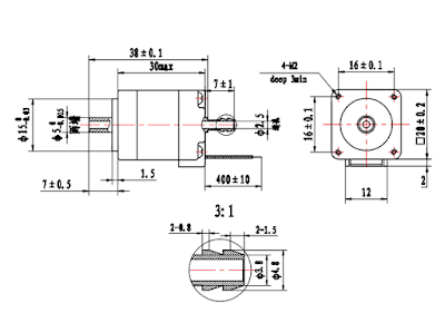
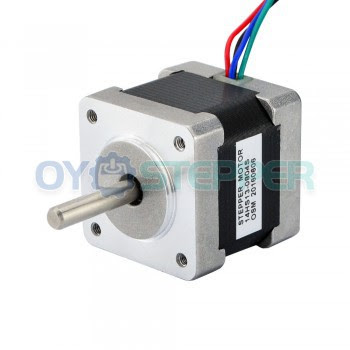
NEMA 14 Frame Size(35 x 35mm)
1.8° Step Angle
High Torque - Up to 56.6 oz-in
High Step Accuracy and Resolution
Low Vibration and Noise
CE Certified and RoHS
Can be Customized for
-Winding Current
-Shaft Options
-Cables and Connectors
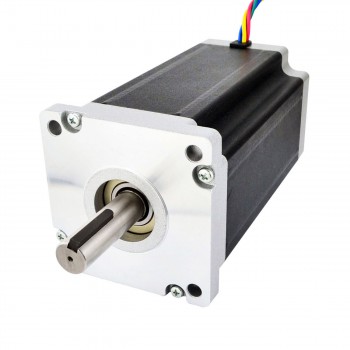
Typical Applications of 14 Stepper Motor: Inject printers, Analytical and Medical Instruments, High Speed Dome Camera, Textile Equipment, Precision Telescope Positioning Systems, Embroidery Machine and Robotics
cnc stepper motor/step motor/stepper motor/Stepper Motor

Typical Applications of 14 Stepper Motor


The 14HS13-0804S Stepper Motor was developed primarily for users who have a restricted installation depth available and where a stepper motor with a construction size of 28 mm Stepper Motor is too long and a construction size of 39 mm Stepper Motor is too big. With the highest possible torque the Nema 14 Stepper Motor for sale series offers a high resolution and is deployed with low-priced power drive for applications in the precision device construction. We have 8-Lead Stepper Motor that can be connected in all possible configurations: series, unipolar, or parallel, to allow the maximum flexibility for your application. We can also customize Nema 14 Stepper Motor's winding to perfectly match voltage, current, and maximum operating speed to meet your requirements.

Need help choosing the right Stepper Motor? Read this: Uni-polar vs Bi-polar or learn more about Stepper Motor Basics.
Friday, July 13, 2018

Operating Instructions of Linear Stepper

In order for the linear stepper motor to operate properly, it will need to be connected to a motion controller or indexer and a stepper motor driver (with power supply). See diagram 1 for operation flow.


Operating Instructions of Linear Stepper


Step 1. A program or motion profile will be written on a PC or laptop and downloaded to the motion controller/indexer. This program will contain parameters such as speed, acceleration, deceleration, desired move, etc…

Step 2. Based on the program parameters, the motion controller/indexer will command the needed number of steps in the desired direction in order to move the desired amount.

Step 3. The microstepping driver will take the step & direction input signals and move the motor using the drivers set current. The bus voltage of the microstepping driver determines the max motor speed.

Step 4. The stepper motor linear actuator will move the desired amount at the programmed speed and acceleration. )

Monday, July 9, 2018

Different ways of stepper motors going into linear actuators

Stepper motors that are traditional rotary motors couple to mechanical rotary-to-linear motion devices (often in the form of a threaded shaft that mates with traversing nut or carriage) to produce linear motion. In this actuator setup, the motor output shaft usually couples to the screw to turn it … and advance the nut (or carriage) and attached load. These are usually small designs that go into consumer products or small-stroke applications in industrial machines.

In contrast, true linear stepper motors—which this FAQ covers in more depth—function much like linear-motor types but leverage the same mode of operation as rotary stepper motors to produce linear motion. More specifically, traditional linear-stepper motors (using variable-reluctance operation) have a moving carriage called a forcer with a permanent magnet, laminated steel cores (which the manufacturer cuts into teeth) and coils around the laminated cores. This forcer engages a straight and stationary track called a platen. This linear-stepper part is mostly steel bar cores (which the manufacturer cuts into teeth and plates with nickel). For super-long strokes, installers can put multiple platens end-to-end and have the forcer ride on all of them.

Summary of linear stepper motors
Engineers most commonly use these linear actuators in larger installations; on axes that move heavier loads; and in high-end medical or material-handling applications such as pick-and-place machinery that require extremely high precision. Like rotary equivalents, linear stepper motors or precision linear actuator either use a variable reluctance (just described) or a hybrid mode of operation. A hybrid linear-stepper platen is like that of a variable-reluctance linear stepper. In contrast, the forcer has multiple permanent magnets, magnetic U-shaped cores (with coils around them) and a steel yoke.

True Linear Stepper Motor

Thursday, June 21, 2018

DIAMETER ISN’T EVERYTHING WHEN IT COMES TO STEPPER MOTOR POWER

A stepper motor or step motor or stepping motor is a brushless DC electric motor that divides a full rotation into a number of equal steps. The motor's position can then be commanded to move and hold at one of these steps without any position sensor for feedback (an open-loop controller), as long as the motor is carefully sized to the application in respect to torque and speed.
Switched reluctance motors are very large stepping motors with a reduced pole count, and generally are closed-loop commutated.
DIAMETER ISN’T EVERYTHING WHEN IT COMES TO STEPPER MOTOR POWER

Changing the stack length will generally not impact on the speeds that you can get but it will have a major impact on the torque (turning force) that you are able to achieve.
For example the ZD2N2318 and ZD10N2318 stepper motors are both NEMA 23 motors (therefore 57mm diameter) but the ZD2N2318 is 42mm long whereas the ZD10N2318 is 104 mm long.
The difference in torque between the 2 motors is 0.6Nm for the ZD2N2318 and 2.4Nm for the 17hs19-2004s. The difference in stack length of a motor with the same NEMA rating has therefore quadrupled the possible torque.

Thursday, May 31, 2018

Introduction of the new hollow shaft stepper motor range

Conventional stepper motors cannot accommodate large diameter hollow shafts without sacrificing torque and performance. Torque is dependent on the size of the magnet placed in the rotor. A large diameter shaft reduces space available for the magnet, thus sacrificing torque. Since we’ve moved the magnet from the rotor into the stator stack, we can accommodate a large shaft without sacrificing torque or performance. Oyostepper, the motion component and systems specialist, further expands its range of stepper motors with the new competitively priced HH series hollow shaft motors from its USA distribution partner Applied Motion Products Inc. (AMP).

Large Holow Shaft Up to 11 mm in Diameter
hollow shaft stepper motor

 With high-torque NEMA 17 and 23 motor frame options in a choice of stack lengths, the hollow shaft facilitates direct assembly of a lead screw without the need for a coupling - keeping hardware to a minimum and simplifying design for machine builders. The hollow shaft stepper motor also allows customised shafts or other power transmission components to be quickly added to the motor without the often-long lead times that specials may take and also enables small quantities of specials to be produced at reasonable cost. The internal shaft diameter for the 17 and 23 frame motors is 5 mm and 8 mm respectively. The holding torque across the 2-phase HH series ranges from 0.45 to 2.3 Nm with current ratings from 2 to 3 A per phase (series).
hollow shaft stepper motor

The motors are supplied with a detachable lead/connector pigtail for straightforward installation in the customer’s application. The 200/step/rev motors can be used with stepper drives across the AMP range, including the micro stepper motor for sale ST5 which offers sophisticated current control and multiple motion control options from simple streaming commands to communication. And it works closely with a small number of global motion control manufacturers and with its own in-house design and manufacturing capability the Hampshire based motion specialist offers complete integrated mechatronics assemblies with customised mechanics, gearheads and other power train components. 


Thursday, May 24, 2018

Introduction of how a brushless dc motor works


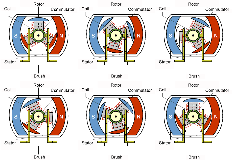
The article Introduction of How A Brushless DC Motor Works explains how brushless dc motor for sale works. In a typical dc motor, there are permanent magnets on the outside and a spinning armature on the inside. The permanent magnets are stationary, so they are called the stator. The armature rotates, so it is called the rotor. The armature contains an electromagnet. When you run electricity into this electromagnet, it creates a magnetic field in the armature that attracts and repels the magnets in the stator. So the armature spins through 180 degrees. To keep it spinning, you have to change the poles of the electromagnet. The brushes handle this change in polarity. They make contact with two spinning electrodes attached to the armature and flip the magnetic polarity of the electromagnet as it spins.
brushless dc motor for sale


This setup works and is simple and cheap to manufacture, but it has a lot of problems:
  • The brushes eventually wear out.
  • Because the brushes are making/breaking connections, you get sparking and electrical noise.
  • The brushes limit the maximum speed of the motor.
  • Having the electromagnet in the center of the motor makes it harder to cool.
  • The use of brushes puts a limit on how many poles the armature can have.
With the advent of cheap computers and power transistors, it became possible to "turn the motor inside out" and eliminate the brushes. In a brushless dc motor (bldc), you put the permanent magnets on the rotor and you move the electromagnets to the stator. Then you use a computer (connected to high-power transistors) to charge up the electromagnets as the shaft turns. This system has all sorts of advantages: Because a computer controls the motor instead of mechanical brushes, it's more precise. The computer can also factor the speed of the motor into the equation. This makes brushless motors more efficient.
·There is no sparking and much less electrical noise.
·There are no brushes to wear out.           
·With the electromagnets on the stator, they are very easy to cool.
·You can have a lot of electromagnets on the stator for more precise control.
brushless dc motor for sale

An el­ectric motor is all about magnets and magnetism: A stepper motor for sale uses magnets to create motion. If you have ever played with magnets you know about the fundamental law of all magnets: Opposites attract and likes repel. So if you have two bar magnets with their ends marked "north" and "south," then the north end of one magnet will attract the south end of the other. On the other hand, the north end of one magnet will repel the north end of the other (and similarly, south will repel south). Inside an electric motor, these attracting and repelling forces create rotational motion. The motor being dissected here is a simple electric motor that you would typically find in a toy.

Thursday, May 17, 2018

Using way of the micro step motor


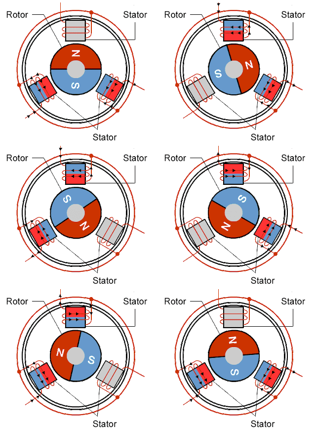
A stepper motor is a special type of brushless DC motor.  Electromagnetic coils are arranged around the outside of the motor. The center of the motor contains an iron or magnetic core attached to a shaft. By sequencing the voltage of the coils precise rotational control can be achieved at relatively low cost. The drawback is, the control is generally open loop, so the system does not know if the motor stalls or gets out of sync with the controller. How do you know if your stepper motor is a unipolar or a bipolar stepper motor just by looking at it? There are three main ways (yes, stepper motors do have a lot of variation) that a stepper motor can be driven. These three driving styles are full-step drive, half-step drive, and micro stepper motor for sale. Full-step drive always has two electromagnets (or at least two different current flows) energized at the same time. In most cases, the motor you are looking at is both. Unipolar and bipolar are just modes that you can use to run the stepper motor. 
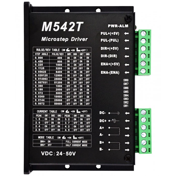
Nema 23 Stepper Motor Drive 24-50VDC 1.5A-4.5A 256 Microstep M542T
The only time a stepper motor is not able to be run in either mode is when there are only four wires coming out of the stepper motor, corresponding to the both ends of the two coils and no central tap wire. If you do have more than four wires, (whether five, six, or even eight wires) at least one of those wires is a center tap wire. You can figure out which wire is which by either looking up the datasheet for your motor or measuring the resistance between two wires at a time with a multi-meter. If one particular wire always measures half of the resistance that other pairs of wires report, then you know that wire must be tapped in the middle (hence half the resistance) of a coil. Despite all of this information, we haven’t actually learned how we can run our motors. To rotate the central shaft, one of the current flows is shut off, “turning off” the electromagnet, and a different current flow is started “turning on” another electromagnet. This driving style has the most torque because two electromagnets are always energized but also has the largest step size. The half-step drive is similar to the full-step drive, but switches between having one or two electromagnets energized. 

One electromagnet will start out energized and then a second one will be “turned on”. Next, the first electromagnet will be “turned off” while leaving the second electromagnet energized. A new current flow will then be started to energize the “third” electromagnet in addition to the second electromagnet being “turned on”. This driving style results in half of the step size of the full-step drive, allowing for more precision, but also results in less torque because there are not always two electromagnets that are energized. Microstepping, such as the nema 42 stepper motors for sale that must have a stronger power than nema 8 stepper motor for sale that you probably suspect, has the smallest step size out of these driving styles. 
Dual Shaft Nema 42 CNC Stepper Motor 30Nm (4248oz.in) 8A 110x201mm 4 Wires
The way it works is by applying a variable amount of voltage to each of the coils in a sinusoidal fashion. The smaller voltage (and thus current flow) increments you are able to produce, the smaller the step size. However, this also results in a variable amount of torque that the stepper motor exhibits, depending on where you are in the step sequence. Most drivers have a thermal protection feature that disables the driver for a brief period of time to allow it to cool.  If you are loosing steps or hear a ticking or pulsing sound from your motors, it could be due to thermal shutdown.

How to enhance the control capability of linear guide rails?

1.Brief of linear guide rail A linear guide rail is a mechanical component used in linear motion systems to guide and support a moving carr...