Wednesday, November 27, 2019

Design Tips for Using Step Motors

A Step Motor is defined as a device whose normal shaft motion consists of discrete angular movements of essentially uniform magnitude when driven from a sequentially switched DC power supply. A step motor is a digital input-output device. It is particularly well suited to the type of application where control signals appear as digital pulses rather than analog voltages.


Parallel connect the lead wires for best torque over the widest speed range
NEMA Frame Stepper MotorsIf not enough current is available from the drive, series connect the lead wires for full torque at low speeds
Keep motor case temperature below 100 °C. This can be achieved by lowering the motor current or limiting the duty cycle
Allow sufficient time to accelerate load
Use a microstepping drive for smoothest motor performance over a wide speed range
For open loop operation, size the motor with a 30-50% torque margin at speed. Including an encoder in the system and using  a Stall Prevention feature may allow operation all the way down to a 0% torque margin
Do not disassemble motors.   A significant reduction in motor performance will result
Do not machine shafts without consulting Electromate® first
Do not disconnect motor from drive while power is applied. Remove power from the drive before disconnecting the motor
Do not use holding torque/detent torque of motor as fail-safe brake
Use an Electromate® recommended stepper drive with your step motor to ensure optimal performance.

Electromate® sells a family of 2-phase hybrid type step motors with a 1.8° step angle in NEMA frame sizes from NEMA 6, NEMA 8,nema 11  to NEMA 42 motor. Stepper motors from Electromate® are available in 4, 6 or 8 lead configurations for bipolar or unipolar operation. All motors can be wired in series or parallel, depending on the requirement. Motors are available with optional rear shaft extensions, encoders, brakes, cables, gearboxes and IP65 sealing.

https://www.voubs.com/user/betty-alan/167261/fullinfo

Saturday, November 23, 2019

How to Choose stepper motor power supplies?

Stepper motors are sensitive to the performance of their power supplies. Stepper motor power supplies can affect:


When sizing a power supply, keep the above points in mind and remember that the drive type and method of operation influence which power supply is most suitable. Read FAQ: What is a stepper driver and how do they work?

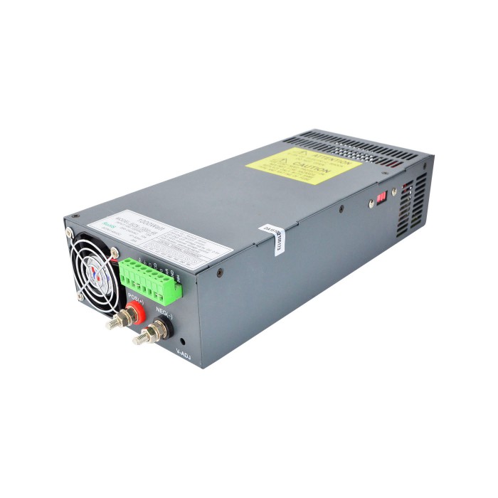
1000W 48V 21A 115/230VAC Switching Power Supply Stepper Motor CNC Kits

Manufacturers offer integrated stepper motors that combine drives and controllers. This one by AMCI takes a power supply of 3.4 A.

When sizing a power supply, ensure that enough power is available when needed — but remember that an overly large supply wastes power.

Note that when it comes to a motor’s rated voltage versus voltage supply, there’s not much concern unless the power supply runs near the drive’s maximum rating. If this is indeed the case, then there’s a risk when decelerating the motor. The load’s momentum stores energy that must be dissipated. The drive can’t do this, so the energy returns to the power supply. This in some cases can overload the power supply and make it fail. So ensure the power supply has a rated voltage well above the motor’s rated voltage. Note that back EMF can also serve as a sort of feedback or gauge of how the motor is running if needed.

There’s additional reason to ensure that voltage is sufficiently high. As the motor draws more current, voltage in unregulated power supplies drops. This can degrade motor performance. In contrast, regulated power supplies provide stable voltage —is useful for applications with high-speed operation.

In the end, specific cnc power supply types from different manufacturers require specific analysis for sizing. Refer to documentation and always contact the manufacturer with questions.

Thread holes on nema 17 arent deep enough? Need suggestion

Merits and demerits of closed loop control system

A closed-loop step motor system combines the advantages of servo motor and stepper motor technologies. Functionally, a closed-loop stepper motor system will run much more smoothly and with less resistance than a standard stepper motor setup. Since a closed-loop system provides feedback and control as well as short transient and free oscillation times, the closed-loop system will not lose or gain steps.

A closed-loop stepper motor system, such as the CL86T & , 34HS59-5004D-E1000 may be the best option when the application requires improved energy efficiency and smoothness of operation, especially at high loads. In addition, a closed-loop system has the advantage over servo motor systems of higher torque at low RPMs. Additional benefits include short transient times, less packaging, accurate/correct positioning using feedback from encoders integrated into the motor(s) to the controller, and comparatively low prices.

Open-loop vs. Closed-loop efficiency
To measure the relative efficiency of an open-loop vs. closed-loop system, assume we repeat the same test with the same two motors of equal size. This time we have the closed-loop and open-loop motors run side by side with the same inertial loads but run programming that holds the move profiles constant and equal, so that both systems perform the same amount of work.

Merits and demerits of closed loop control system


open-loop vs. closed-loop
This is a Relative Comparison Chart for StepSERVO closed-loop systems versus open-loop systems. Note the superior performance of the closed-loop stepper system as demonstrated in the results of laboratory testing that compare two systems for acceleration (torque), efficiency (power consumption), position error (accuracy), heat generation, and noise levels.

While the two motors index the same move profile repeatedly, current draw from the dc power supply feeding the two systems is measured and power consumption is calculated. As can be seen in value plots, average power consumption of the open-loop stepper system is 43.8 watts, while that of the closed-loop system is only one third as much — 14.2 watts on average. This dramatic difference in power consumption clearly shows the higher efficiency operation of the closed-loop system. Any user looking to increase the system efficiency of their open-loop stepper system can now consider a simple upgrade to a closed-loop system and expect significantly lower consumption.

Some difference between servo motor and closed-loop stepper motors?

Friday, November 22, 2019

Nema23 vs Nema17 Stepper Motor for the engineering challenged

My wife and I have started designing a CNC/3D printer hybrid. I over engineered some structural designs so now my YZ assembly is a bit weighty (to say the least). dual 20mm linear shatfs with pillow blocks...I failed to look into the weight per meter before buying eye rolling smiley.

Nema 23 vs Nema 17 for the engineering challenged


I planned all along on using Nema 23's for the z axis and haven't decided on Nema 17's or 23's for X or Y, and still deciding on Nema17's or Nema 11's for the extruder.

I also like the looks, and thought that has gone into the design of the PrintrBoard.

Can anyone with more experience and or knowledge shed some light here. Am I over thinking this as well?
I have listed some assumptions I am working with and would appreciate any input what-so-ever. (even if it's a "You idiot, read this!" winking smiley )

1) I haven't seen many mixed motor builds discussed, and am assuming that is due to limitations in regulating power supplies in order to deliver the different current/voltage profiles for the different motors.

2) And I suspect that if I am correct in #1 then this is even more of an issue when using a unified controller/driver board like the PrintrBoard.

3) Also I haven't been able to find any documentation on the PrintrBoard, or Polulo as to whether or not you can drive Nema 23's with them without burning them up (Polulo specifically mentions using Nema 17's but not that it is a requirement/limitation).

4) I do know that Simply stating Nema23 and/or Nema 17 is not enough of a consideration, as these numbers are more a designation of footprint than power needs, however what specs do I need to be most concerned with when I am trying to source these, especially if I am looking at trying to mix them in a build?

https://uberant.com/article/638854-which-has-higher-torque-nema-17-or-nema-2365311/

https://article-realm.com/article/Writing-and-Speaking/Article-Writing/3754-How-to-choose-the-NEMA-23-or-the-NEMA-34-stepper-motors.html


Thursday, November 21, 2019

Current and voltage we need to supply to the stepper motors

So you’ve decided how many stepper motors you need and the torque rating. It’s then just a matter of matching to a suitable controller. All controllers will have stepper drivers that either individual modules or integrated into the controller board. The digital stepper drivers are designed to supply current and voltage, which in most cases is adjustable. It’s important to match the current with the stepper motor. Stepper motors can work at very low voltages but they are usually driven at much higher voltages up to 8 times by a chopper driver. If you would like more information check this link This gives higher torque and speed.

Current and voltage we need to supply to the stepper motors


If you use a stepper that needs 2.8 amps and your drivers only supplies 1.5 amps it may still work but slowly and may not be enough to overcome the load.

Generally, NEMA17’s are run on 12 volts and NEMA23 24 volts. If you supply less then the motors will turn slowly. Its to do with something called back EMF. So when you are deciding on the controller check the current rating of the steppers and make sure the controller or driver modules can be adjusted to match as close as possible but don’t supply more or the motor may fail.

My foam cutter uses 57BYGH56-401A NEMA 23 which are rated at 2.8 amps and 3.36 Volts per phase. I run this with a 24-volt power supply and the current is at 2.25 amps set via DIP switches on the board. This has run for several years without any issues

Power Supply
The CNC power supply needs to be able to deliver the voltage and current for your chosen motors and controller. Going bigger on the current won’t hurt but the voltage needs to match the controller’s voltage. So for my foam cutter, I use 4 x 23HS22-2804S NEMA 23 rated at 2.8 amps and the controller need 2 amp. So 4 x 2.8 amps plus 2 amps for the controller gives 13.2 amps. If we multiply that by 24 volts to give Watts that comes to 316.8 Watts. Powers supplies can be rated by Amps or Watt so I use a 15 Amp 350 Watt supply.

CNC controllers for the DIY machine

Friday, November 15, 2019

Stepper Motors For Hot Wire CNC Foam Cutters

When we cut foam with a hot wire foam cutting machine it’s not actually being cut but melted.  Its referred to as cutting by radiance.  So the load on the steppers motors is virtually nothing from the hot wire if its temperature and feed rate are correct.  Nearly all of the load comes from the weight of the moving parts of the machine.

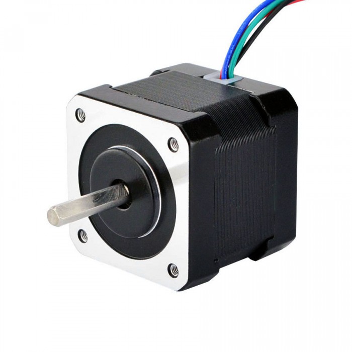
Nema Size 17 Stepper Motor Bipolar 45Ncm (64oz.in) 2A 42x40mm 4 Wires w/ 1m Cable & Connector for DIY 3D Printer CNC Rob

So NEMA17’s should be fine if your machine is not too heavy, something around 50-80 oz/in should be OK.  Vortec RC uses NEMA17 on their kit. www.vortex-rc.com/product/4-axis-diy-hot-wire-cnc-for-rc-hobbyists-aeromodellers-and-designers/
FoamLinx offer several machines but these are not really aimed at hobbyist, costing several thousand dollars. However, we can see they are using NEMA23 rated at 220oz/in on their small machine.


My current CNC foam cutter uses NEMA23 motor 175oz/in rated at 2.8 Amps. The moving parts on my build weigh a little over 11KG or 25 lbs, so it’s a bit on the heavy side. It’s made from 3/4″ (18mm) High-Density FIbreBoad(HDF) which is very strong and stable but quite heavy. So I decided to use the bigger stepper motors with the recommended 24 Volt power supply.

My updated design for 2019 which will use 12mm MDF and features several changes and improvements. It reduces weight considerably and allows the use of NEMA17 steppers. Keep checking back for the updated design should be out soon.

http://www.apsense.com/article/whats-the-difference-among-4wire6wire8wire-step-motor.html
https://www.techsite.io/p/1278002


Wednesday, November 13, 2019

How to Prevent Step Loss of Stepper Motor

The use of stepper motors is an excellent choice. However, a key concern is step losses. Step losses can be prevented or corrected in most instances.prevent step loss in stepper motors.

How to Prevent Step Loss of Stepper Motor


Stepper motors for sale operate open loop.  When a stepping motor does not operate correctly in a specific situation, the common conclusion is that either the drive electronics or the motor is faulty. The motor selection and the choice of the driver are critical.  However, other factors contribute to step losses.

The following points are important to examine for the analysis of step losses or non-operation in a methodical fashion across a variety of applications:

Stepper Motor Selection
Motion profile
Start-Stop operation
Trapezoidal profile
External commutation errors
External events
Back driving
Increase of the pay load over time

Stepper Motor Selection
The first task is to select the right stepper motor for the application. For the best selection, those basic theoretical rules have to be respected:

Select the motor based on the highest torque/speed point required by the application (selection based on the worst case)
Use a 30% safety factor from the published torque vs. speed curve (pull-out curve).
Ensure that the application cannot be stalled by external events
It is important to remember that a stepper motor does not operate like a DC motor. There is no working point parameterization, and the phase current does not increase to overcome variations of load. As long as the speed vs. torque requirement of the application is within the specs of the motor, no problem will be encountered. If this requirement is out of the specs, the motor stalls (OK or NOT OK functionality). In any case, the current in the phases is not changing and adapting by itself to the situation.

To read the complete technical paper and learn more about how to prevent step losses and tips for troubleshooting, download the free 4-page pdf now by clicking the button below.

What's the Difference Among 4-Wire,6-Wire,8-Wire Step motor
The difference Bettween 1-phase, 2-phase and 3-phase Motor


Friday, November 8, 2019

Related to one-two phase-on stepper driving is microstepping

A stepper drive is the driver circuit that controls how the stepper motor operates. Stepper drives work by sending current through various phases in pulses to the stepper motor(23hs45-4204s17hs16-2004s1.) There are four types: wave drives (also called one-phase-on drives), two-phase on, one-two phase-on drives and microstepping drives.
Microstepping delivers very fine motion resolutions. Here, the drive uses current regulation to prevent torque oscillations. With this technique, engineers can use stepper motors in more applications.
In sort, a drive that is microstepping increases and decreases current along a sine wave, so no pole is fully on or off. Here is a sample microstepping sine-wave current:
Stepper Drive Microstepping Current Sine-Wave
Note the subtle jagged contour of the sine-wave current. While microstepping doesn’t necessarily improve accuracy, it does get higher resolution than other driving modes—which is particularly helpful for applications in which the motor goes through no-load situations. During operation, motors can miss steps. However, microstepping spreads energy out instead of delivering it to the motor all at once, which can cause ringing and overshoot.
For all of these forms of driving, the motors can have different windings. Unipolar stepper motors nema 17 only accept positive voltage. Unipolar requires an extra wire in the middle of every coil to let current flow from one end to the other. Bipolar stepper motors use both positive and negative voltage. Bipolar stepper motors have more torque because they produce a stronger magnetic field, but their construction also requires more wire.

Friday, November 1, 2019

Safe Installation of Stepper Motor for 3D Printer

Installing steppers is a fairly straightforward process thanks to the standardized connectors used by most manufacturers. Simply plug the motor into the correct slot of the control board, and you should be good to go. However, there are still a few things to watch out for:

Safe Installation of Stepper Motor for 3D Printer


First, never install a motor (or anything, for that matter) on a printer while it is on and plugged in. This is hazardous because if done incorrectly, you risk shocking yourself, frying delicate components, and starting an electrical fire. So please, power off the printer and unplug it before commencing work.

Second, never unplug a step motor that is being powered. If you paid attention to the first step, this isn’t a problem, but if you didn’t, you’ll likely end up frying your stepper driver, and possibly your control board.

Third, ensure your digital stepper drivers are supplying the correct amount of current to the motors. This can be adjusted through the potentiometers on the driver board, or in some cases through the software of the printer. Too little current means the motor won’t have the proper torque, and too much can cause it to overheat.

Lastly, if you notice anything obviously wrong with the operation of the motor after installation, stop whatever you are doing and power down the printer. Carefully examine your wiring and driver circuit to ensure there are no mistakes before continuing to use the motor (if there aren’t any, make sure the motor, driver, and software are all compatible). This is a safe habit to assume while working with electronics to avoid fires and fried components.

Code Explanation to control Nema 17 with Arduino
Circuit diagram to control Nema17 stepper motor with Arduino


How to achieve innovation in hybrid stepper motors?

 Hybrid stepper motor is a type of motor that combines permanent magnet and reactive stepper motors. It has the advantages of high efficienc...