Thursday, May 31, 2018

Introduction of the new hollow shaft stepper motor range

Conventional stepper motors cannot accommodate large diameter hollow shafts without sacrificing torque and performance. Torque is dependent on the size of the magnet placed in the rotor. A large diameter shaft reduces space available for the magnet, thus sacrificing torque. Since we’ve moved the magnet from the rotor into the stator stack, we can accommodate a large shaft without sacrificing torque or performance. Oyostepper, the motion component and systems specialist, further expands its range of stepper motors with the new competitively priced HH series hollow shaft motors from its USA distribution partner Applied Motion Products Inc. (AMP).

Large Holow Shaft Up to 11 mm in Diameter
hollow shaft stepper motor

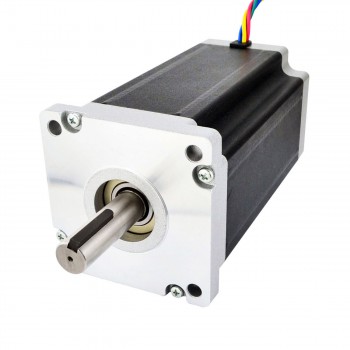
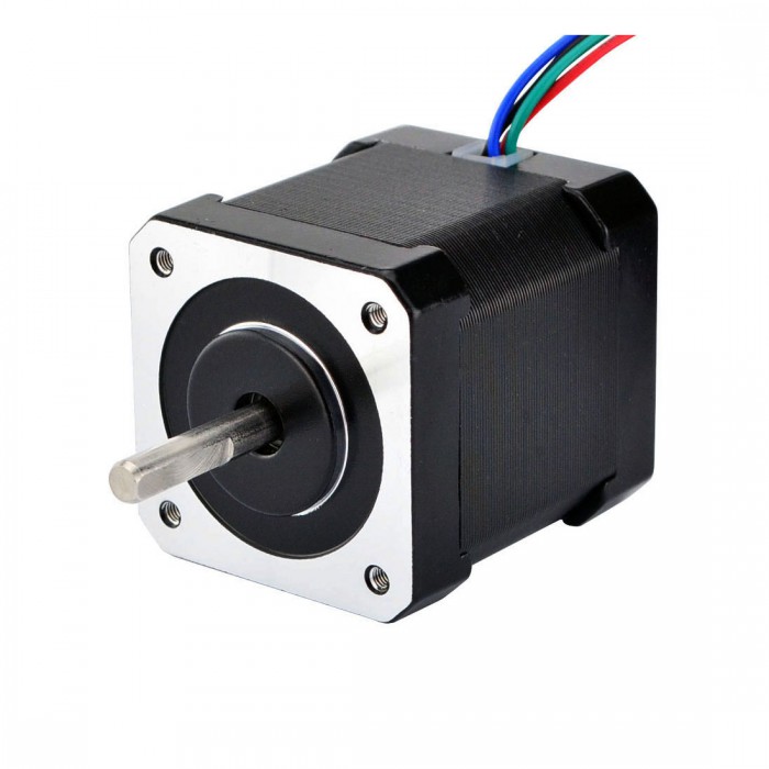
 With high-torque NEMA 17 and 23 motor frame options in a choice of stack lengths, the hollow shaft facilitates direct assembly of a lead screw without the need for a coupling - keeping hardware to a minimum and simplifying design for machine builders. The hollow shaft stepper motor also allows customised shafts or other power transmission components to be quickly added to the motor without the often-long lead times that specials may take and also enables small quantities of specials to be produced at reasonable cost. The internal shaft diameter for the 17 and 23 frame motors is 5 mm and 8 mm respectively. The holding torque across the 2-phase HH series ranges from 0.45 to 2.3 Nm with current ratings from 2 to 3 A per phase (series).
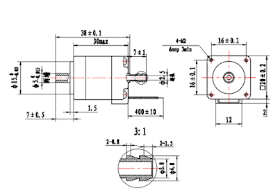
hollow shaft stepper motor

The motors are supplied with a detachable lead/connector pigtail for 
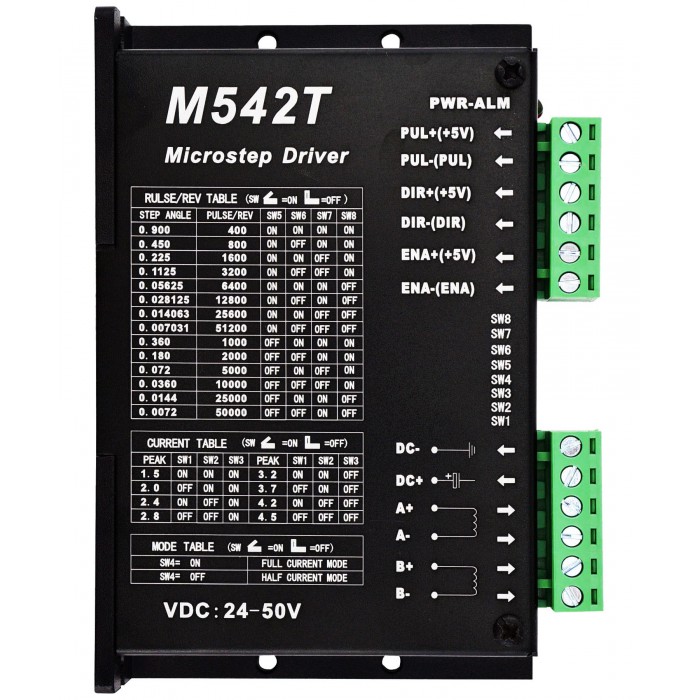
straightforward installation in the customer’s application. The 200/step/rev motors can be used with stepper drives across the AMP range, including the micro stepper motor for sale ST5 which offers sophisticated current control and multiple motion control options from simple streaming commands to communication. And it works closely with a small number of global motion control manufacturers and with its own in-house design and manufacturing capability the Hampshire based motion specialist offers complete integrated mechatronics assemblies with customised mechanics, gearheads and other power train components. 


Thursday, May 24, 2018

Introduction of how a brushless dc motor works


The article Introduction of How A Brushless DC Motor Works explains how brushless dc motor for sale works. In a typical dc motor, there are permanent magnets on the outside and a spinning armature on the inside. The permanent magnets are stationary, so they are called the stator. The armature rotates, so it is called the rotor. The armature contains an electromagnet. When you run electricity into this electromagnet, it creates a magnetic field in the armature that attracts and repels the magnets in the stator. So the armature spins through 180 degrees. To keep it spinning, you have to change the poles of the electromagnet. The brushes handle this change in polarity. They make contact with two spinning electrodes attached to the armature and flip the magnetic polarity of the electromagnet as it spins.
brushless dc motor for sale


This setup works and is simple and cheap to manufacture, but it has a lot of problems:
  • The brushes eventually wear out.
  • Because the brushes are making/breaking connections, you get sparking and electrical noise.
  • The brushes limit the maximum speed of the motor.
  • Having the electromagnet in the center of the motor makes it harder to cool.
  • The use of brushes puts a limit on how many poles the armature can have.
With the advent of cheap computers and power transistors, it became possible to "turn the motor inside out" and eliminate the brushes. In a brushless dc motor (bldc), you put the permanent magnets on the rotor and you move the electromagnets to the stator. Then you use a computer (connected to high-power transistors) to charge up the electromagnets as the shaft turns. This system has all sorts of advantages: Because a computer controls the motor instead of mechanical brushes, it's more precise. The computer can also factor the speed of the motor into the equation. This makes brushless motors more efficient.
·There is no sparking and much less electrical noise.
·There are no brushes to wear out.           
·With the electromagnets on the stator, they are very easy to cool.
·You can have a lot of electromagnets on the stator for more precise control.
brushless dc motor for sale

An el­ectric motor is all about magnets and magnetism: A stepper motor for sale uses magnets to create motion. If you have ever played with magnets you know about the fundamental law of all magnets: Opposites attract and likes repel. So if you have two bar magnets with their ends marked "north" and "south," then the north end of one magnet will attract the south end of the other. On the other hand, the north end of one magnet will repel the north end of the other (and similarly, south will repel south). Inside an electric motor, these attracting and repelling forces create rotational motion. The motor being dissected here is a simple electric motor that you would typically find in a toy.

Thursday, May 17, 2018

Using way of the micro step motor


A stepper motor is a special type of brushless DC motor.  Electromagnetic coils are arranged around the outside of the motor. The center of the motor contains an iron or magnetic core attached to a shaft. By sequencing the voltage of the coils precise rotational control can be achieved at relatively low cost. The drawback is, the control is generally open loop, so the system does not know if the motor stalls or gets out of sync with the controller. How do you know if your stepper motor is a unipolar or a bipolar stepper motor just by looking at it? There are three main ways (yes, stepper motors do have a lot of variation) that a stepper motor can be driven. These three driving styles are full-step drive, half-step drive, and micro stepper motor for sale. Full-step drive always has two electromagnets (or at least two different current flows) energized at the same time. In most cases, the motor you are looking at is both. Unipolar and bipolar are just modes that you can use to run the stepper motor. 
Nema 23 Stepper Motor Drive 24-50VDC 1.5A-4.5A 256 Microstep M542T
The only time a stepper motor is not able to be run in either mode is when there are only four wires coming out of the stepper motor, corresponding to the both ends of the two coils and no central tap wire. If you do have more than four wires, (whether five, six, or even eight wires) at least one of those wires is a center tap wire. You can figure out which wire is which by either looking up the datasheet for your motor or measuring the resistance between two wires at a time with a multi-meter. If one particular wire always measures half of the resistance that other pairs of wires report, then you know that wire must be tapped in the middle (hence half the resistance) of a coil. Despite all of this information, we haven’t actually learned how we can run our motors. To rotate the central shaft, one of the current flows is shut off, “turning off” the electromagnet, and a different current flow is started “turning on” another electromagnet. This driving style has the most torque because two electromagnets are always energized but also has the largest step size. The half-step drive is similar to the full-step drive, but switches between having one or two electromagnets energized. 

One electromagnet will start out energized and then a second one will be “turned on”. Next, the first electromagnet will be “turned off” while leaving the second electromagnet energized. A new current flow will then be started to energize the “third” electromagnet in addition to the second electromagnet being “turned on”. This driving style results in half of the step size of the full-step drive, allowing for more precision, but also results in less torque because there are not always two electromagnets that are energized. Microstepping, such as the nema 42 stepper motors for sale that must have a stronger power than nema 8 stepper motor for sale that you probably suspect, has the smallest step size out of these driving styles. 
Dual Shaft Nema 42 CNC Stepper Motor 30Nm (4248oz.in) 8A 110x201mm 4 Wires
The way it works is by applying a variable amount of voltage to each of the coils in a sinusoidal fashion. The smaller voltage (and thus current flow) increments you are able to produce, the smaller the step size. However, this also results in a variable amount of torque that the stepper motor exhibits, depending on where you are in the step sequence. Most drivers have a thermal protection feature that disables the driver for a brief period of time to allow it to cool.  If you are loosing steps or hear a ticking or pulsing sound from your motors, it could be due to thermal shutdown.

Tuesday, May 15, 2018

How to work out the stepper motor power supply voltage

If you have a target travel speed for your printer, you can work out at least approximately what supply voltage you will need to the motor drivers. Here's how, with an example calculation:
Decide on your target travel speed. For this example I will use 200mm/sec.
From the target travel speed, work out the worst-case maximum belt speed. For a Cartesian printer, the worst case is a pure X or Y motion, so the worst case belt speed is the same as the travel speed. For a CoreXY printer, the worst case is a diagonal motion and the corresponding belt speed is sqrt(2) times the travel speed. For a delta printer the worst case is a radial move near the edge of the bed and the worst case belt speed is the travel speed divided by tan(theta) where theta is the smallest angle of a diagonal rod to the horizontal. In practice we can't use the target travel speed for radial moves right up to the edge of the bed because of the distance needed to accelerate or decelerate, so take theta as the angle when the nozzle is about 10mm from the edge of the bed opposite a tower. For my delta this is 30 degrees, so the maximum belt speed is 200/tan(30deg) = 346mm/sec.
Nema 17 Stepper Motor Bipolar 59Ncm (84oz.in) 2A 42x48mm 4 Wires w/ 1m Cable & Connector(17HS19-2004S1)
Work out the motor revs per second at the maximum belt speed, by dividing the belt speed by the belt tooth pitch (2mm for GT2 belts) and the number of teeth on the pulley. My delta uses 20-tooth pulleys so the maximum revs per second is 346/(2 * 20) = 8.7.
Work out the peak back emf due to inductance. This is revs_per_second * pi * motor_current * motor_inductance * N/2 where N is the number of full steps per revolution (so 200 for 1.8deg motors, or 400 for 0.9deg stepepr motors or 1.8 degree stepper motor). My motors are 0.9deg with 4.1mH inductance and I generally run them at 1A. So the back emf due to inductance is 8.7 * 3.142 * 1.0 * 4.1e-3 * 400/2 = 22.4V.
Work out the approximate back emf due to rotation. From the formula given earlier, this is sqrt(2) * pi * rated_holding_torque * revs_per_second / rated_current. My motors have rated current of 1.68A and holding torque of 0.44Nm, so the result is 1.414 * 3.142 * 0.44 * 8.7/1.68 = 10.1V.
Preferably, the driver supply voltage should be at least the sum of these two back emfs, plus a few more volts. If you have two motors in series then the required voltage is doubled.
In my example, this gives 32.5V, which is above the 25V recommended input voltage for the Duet 2. But at least we know that for a worst-case delta move with 200mm/sec travel speed, if I use a 24v stepper motor supply then that is more than 2/3 of the theoretical value, so the torque available for that move should not drop off by more than about 1/3 of the usual torque available. On the other hand, a 12V supply would clearly be inadequate - which explains why I was only able to achieve 150mm/sec before I upgraded the printer to 24V.

Source from:
 https://blog.oyostepper.com/2018/04/25/how-to-work-out-the-stepper-motor-power-supply-voltage/

Thursday, May 10, 2018

The way to prevent stepper motor losing step

Stepper motor is an open-loop control motor which transforms electric pulse signal into angular displacement or linear displacement. In the case of no step losses, the motor speed and stop position depend on the pulse signal frequency and the pulse count instead of the variation of the load. When the stepper motor receives a pulse signal, the motor will rotate a fixed angle (step angle) according to the setting direction.

How to prevent stepper motor losing step?
Actually, the reason for the stepper motor losing step is essentially the improper choice of stepper motor driver. Only by choosing the right and appropriate stepper motor driver can the stepper motor exert its precise control advantages. Selecting the right stepper motor driver requires a driver greater than or equal to the current according to the current of the motor. If a low vibration or high accuracy is required, a subdivided drive can be used. For large torque motor, high voltage type actuator is used as far as possible to obtain good high speed performance.
At the same time for the driver, many people directly use the switching mode power supply as the drive power supply. However, it is generally better not to use switching power supply, especially for the high torque stepper motor, unless switching power supply is more than twice as much as the required power. When the motor works, it is a large inductance load, the power supply will form instantaneous high pressure. The switching power supply overload performance is not good and it will protect the shutdown. And its precise voltage stabilization performance is not needed. Sometimes it may cause the switching power supply and the drive damage. For the driving power of the stepping motor, the DC power supply can be replaced by the conventional toroidal or R transformer.

The production of the hybrid stepper motor resonance is that the pulse frequency of the motor is equal to the natural frequency of the stepper motor, and the frequency is related to the subdivision of the driver. When we use stepper motor, the subdivision ability of the actuator is very important. The smaller the resonance range is, the better is. The large load interia is caused by the overload of stepper motor. Aimed at this situation, we should avoid the motor overload in the use.

Industrial Applications of NEMA 42 Stepper Motor

Source:https://blog.oyostepper.com/2018/05/11/the-way-to-prevent-stepper-motor-losing-step/

Saturday, May 5, 2018

Something about Stepper Motor Driver You Should Know

What is a Motor Driver?
A digital stepper motor driver is a little current amplifier; the function of motor drivers is to take a low-current control signal and then turn it into a higher-current signal that can drive a motor.

What is a Motor Driver?


Types of Motor Drivers
There are many different kinds of motor drivers. At Future Electronics we stock many of the most common types categorized by maximum supply voltage, maximum output current, rated power dissipation, load voltage, packaging type and number of outputs. The parametric filters on our website can help refine your search results depending on the required specifications.

The most common values for maximum supply voltage are 36 V and 52 V. We also carry motor drivers with supply voltage up to 450 V. The number of outputs can be between 1 and 12, with the most common motor drivers having 1, 2 or 4 outputs.

Motor Drivers from Future Electronics
Future Electronics has a full programmable motor driver selection from several chip manufacturers that can be used for a motor driver IC (integrated circuit), bipolar stepper motor driver, H bridge motor driver, servo motor driver, DC motor driver, brushless motor driver or for any circuit that may require a motor driver. Simply choose from the motor driver technical attributes below and your search results will quickly be narrowed in order to match your specific motor driver application needs.

If you have a preferred brand, we deal with several semiconductor manufacturers such as Freescale Semiconductor, ON Semiconductor, ROHM Semiconductor or STMicroelectronics, among others. You can easily refine your motor driver product search results by clicking your preferred motor driver brand below from our list of manufacturers.

Applications for Motor Drivers:
Analog stepper motor driver can be found in a wide array of applications including:
Relay and solenoid switching
Stepping motor
LED and incandescent displays
Automotive applications
Audio-visual equipment
PC Peripherals
Car audios
Car navigation systems

Tips on how to choosing the proper stepper motor

How to achieve innovation in hybrid stepper motors?

 Hybrid stepper motor is a type of motor that combines permanent magnet and reactive stepper motors. It has the advantages of high efficienc...