Friday, November 30, 2018

High Responsiveness and Excellent Synchronization of Stepper Motor

The third remarkable feature of stepper motors best is responsiveness. The open-loop control, which sends one-way commands to the motor, has a high followup mechanism toward commands. While servo motors, which wait for feedback from the encoder, tend to have "delays" with commands, stepper motors operate synchronously with a pulse. Therefore, there are very few "delays," resulting in excellent response. For this reason, stepper motors are suitable for applications that require synchronous operations of multiple motors. One example is a board transferring application that requires two conveyors, with one motor mounted respectively, to transfer boards in between the two conveyors.

Point 2
Excellent Low / Mid-Speed Range!
Example: Torque of a motor frame size 85 mm is equivalent to a rated torque of a 400 W servo motor when 1000 r/min.

Torque in an even lower speed range can be up to 5 times higher. For a shortdistance positioning, having high torque in the low / mid-speed range is essential.
RKII Torque Chart
Stepper Motor Open Loop vs Servo Closed Loop

Wednesday, November 28, 2018

Driving a unipolar stepper motor with the NXP PCA9537

The NXP PCA9537 is a 10-pin CMOS totem pole GPIO with an SMBus and I2C two-wire bus so it can interface to most microcontrollers (Figure 3).


Figure 3: The NXP PCA9537 is a totem pole GPIO that takes the I2C byte sequences from the host controller and provides the requisite waveforms to the gate inputs G1 through G4. (Image source: NXP)

In the diagram, the motor is a 12-V unipolar nema 23 stepper motor with a current rating of 1.25 A. For users that want to modify the diagram and tweak it to their own application, there is a fully interactive schematic of the unipolar driver available on Schematics.com.

The PCA9537 has a 4-bit configuration register, 4-bit input port register, and a 4-bit output port register, and a 4-bit polarity inversion register for “active high” or “active low” operation. The GPIO has a fixed I2C-bus slave address of 92H and it takes the I2C byte sequences from the host controller and provides the requisite waveforms to the gate inputs G1 through G4.

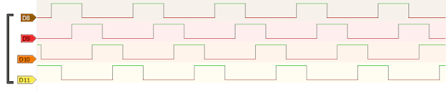
The diagram also shows the NXP PCA9665, an IC that serves as an interface between most standard parallel-bus microcontrollers/microprocessors and the serial I2C-bus allowing the parallel bus system to communicate bidirectional with the I2C-bus. The type of waveform will be one corresponding to wave, two-phase or half-step drive, as chosen by the user. The duration of the pulses is controlled by time delay implemented in the host controller firmware. It is shown as a reference for the various waveforms. The maximum I2C-bus speed supported by PCA9537 is 400 kHz.

To drive the stepper motor best price at approximately 18 RPM, use the following byte sequence, where ‘S’ stands for I2C-bus START condition, and ‘P’ stands for STOP condition. Also, DLY1 and DLY2 are time delays implemented by the microcontroller firmware. Numbers are represented in hexadecimal notation:

S, 0x92, 0x03, 0x00, P // Set all 4 IO pins of PCA9537 as OUTPUT pins;
// IO Configuration Register = 0x00
Set DLY1 = 300 ms // Time delay between steps; 18 RPM for a 7.5˚ motor

//Start of waveform loop
S, 0x92, 0x01, 0x08, P // Start the half-step sequence waveform
Execute time delay between steps = DLY1
S, 0x92, 0x01, 0x0C, P // outputs for the next step
Execute time delay between steps = DLY1
S, 0x92, 0x01, 0x04, P // outputs for the next step
Execute time delay between steps = DLY1
S, 0x92, 0x01, 0x06, P // outputs for the next step
Execute time delay between steps = DLY1
S, 0x92, 0x01, 0x02, P // outputs for the next step
Execute time delay between steps = DLY1
S, 0x92, 0x01, 0x03, P // outputs for the next step
Execute time delay between steps = DLY1
S, 0x92, 0x01, 0x01, P // outputs for the next step
Execute time delay between steps = DLY1
S, 0x92, 0x01, 0x09, P // outputs for the next step
Execute time delay between steps = DLY1
// Loop through waveform sequence to keep running motor
// OR execute next two steps if desired
Execute time delay = DLY2 // Hold in current position for time = DLY2
S, 0x92, 0x01, 0x00, P // Turn off motor

(Byte sequence source: NXP)
Of course, some users may want to drive multiple motors. For this, many single-chip options are also available. In the meantime, it’s good to practice on the PCA9537 and the unipolar, single-motor, interactive schematic shown here.

Saturday, November 24, 2018

A Simple Approach to Driving The Ubiquitous Stepper Motor

Stepper motors for sale are a favorite of designers, engineers, and makers alike, and so can be found almost everywhere there is an electronically controlled system. They’re so popular and useful, in fact, that it’s often easy to forget how they work and to ensure that they are being driven correctly.

The motors themselves are brushless, synchronous DC motors where each 360˚ rotation is divided into a number of equal, discrete steps. The angular rotation of step is determined by the number of “toothed” electromagnets arranged around a central, gear-shaped piece of iron (Figure 1). It is the energization of the magnets, and the ensuing magnetic attraction of the gear-shaped shaft’s teeth, that pulls the shaft around its axis of rotation by.


Figure 1: The permanent-magnet rotor is rotated according to the sequencing of the pulses applied to energize the electromagnetic “teeth”. (Image source: NXP)

It’s important to note that when the shaft’s teeth are aligned with the first electromagnet, they are slightly offset from the next electromagnet. This makes sure that when the next electromagnet is energized, the teeth are pulled in the direction of the next electromagnet.

The number of steps required to complete a single 360˚ revolution defines its resolution, or how finely the motor can be controlled. Typical motors have 200 steps per revolution, but it’s not unusual to see 1600 steps per revolution for very fine control of movement, such as the arm of a hard disk drive.

Control is accomplished using a sequence of square digital pulses, typically from a microcontroller, which are used to intelligently drive the coils. The word “intelligently” is deliberate here: as how the coils are arranged, constructed and driven determines key parameters such as efficiency, accuracy, precision, repeatability, and torque. Each pulse is a discrete step and so the number of pulses and their rate determine the rotation distance and speed.

Depending on how the coils are connected and driven, steppers can be either unipolar or bipolar. In unipolar designs, the current flow is always in the same direction to achieve rotation. In bipolar nema 17 geared, an alternating reversal of current flow in the windings is used to achieve rotation.

Some of the interesting, useful and fun characteristics of stepper motors include that fact that once energized, it stays rock steady with full torque until the next pulse; the precision with which they can be controlled, particularly if gearing is used; the fact that they can be reversed quickly by changing pulse polarity, manually or electronically; their fast-stop capability; robustness and reliability; and low cost.

Adding to the cost and simplicity factor is the fact that they are open loop. This means that there is no need for extra sensors or feedback mechanisms to determine the shaft position.


Thursday, November 15, 2018

Effective way to prevent step losses of stepping motor

The use of stepper motors is an excellent choice. However, a key concern is step losses. Step losses can be prevented or corrected in most instances.

Image result for Effective way to prevent step losses of stepping motor

How to prevent step losses with Stepper Motors
Stepper motors operate open loop.  When a stepping motor does not operate correctly in a specific situation, the common conclusion is that either the motor or the drive electronics is faulty. The motor selection and the choice of the driver are critical.  However, other factors contribute to step losses.
The following points are important to examine for the analysis of step losses or non-operation in a methodical fashion across a variety of applications:

A. Stepper Motor Selection
B. Motion profile
B1. Start-Stop operation
B2. Trapezoidal profile
C. External commutation errors
D. External events
D1. Back driving
D2. Increase of the pay load over time

A. Stepper Motor Selection
The first task is to select the right step motor best price for the application. For the best selection, those basic theoretical rules have to be respected:
1. Select the motor based on the highest torque/speed point required by the application (selection based on the worst
case)
2. Use a 30% safety factor from the published torque vs.speed curve (pull-out curve).
3. Ensure that the application cannot be stalled by external events.

It is important to remember that a stepper motor does not operate like a DC-motor.  There is no working point parameterization, and the phase current does not increase to overcome variations of load. As long as the speed vs. torque requirement of the application is within the specs of the motor, no problem will be encountered. If this requirement is out of the specs, the motor stalls (OK or NOT OK functionality). In any case, the current in the phases is not changing and adapting by itself to the situation.

Tuesday, November 13, 2018

The schematic of stepper driver and power circuit

The schematic is complete. For most motors, the diodes can be usual rectifier types rated at 1A (i.e. 1N4004). Fast rectifier types are usually a better choice. If you're using N-FETs with included protection diodes, there is no need for external diodes. Also, with FET transistors, the gate can be connected directly to Arduino pin, without 1k resistors. Those resistors are required if you use bipolar transistors instead of FETs. Yes, you can use NPN transistors. Darlington transistors are recommended. Just make sure the transistor can handle load current (drain-source current, collector-emitter current) and it can be fully switched on by Arduino (gate threshold voltage, DC gain).

The resistor connected between OUT and ADJ pins of LM317 step driver controls the constant current. For 2.4 ohms, the current is 1.25/2.4 = 0.5A. Use a correct wattage resistor (2-3W). Replace the resistor with a suitable value for the motor rated current. The voltage at LM317 input cannot exceed 35V.


All it needs now is the software. Rotating a stepper is very simple, that's why I wrote my own code instead of using a library. To simplify the code I didn't use standard digitalWrite routines. I wrote directly to the port. First the port must be set as output in setup() with DDRB = 0x3F;. This sets digital pins 8 to 11 as outputs. Check Arduino Port Manipulation page.

The coils must be energized in a specific order: a half of one coil (A), then a half of the other (B). Pulses should then energize the remaining coil halves (C half of the first coil, then D half of the other coil). The order determines direction. Just remember: you should not energize in a sequence one half of a coil, then the other half of the same coil. The motor will make a step in one direction and one step backwards. It doesn't harm the motor though. A-B-C-D and A-D-C-B are valid sequences, but A-C-B-D is not.

Because you can power 4 coils, there are actually 3 ways of doing it. You can use wave drive. Each of the 4 coils is powered sequentially so that only one coil is powered an any time. This results in less power consumption and less torque. Below is the pulse train and the code used to generate it.

void waveDrive(unsigned int numSteps, unsigned int stepDelay = 5) {
  for (unsigned int i = 0; i < numSteps; i++) {
    PORTB = B00000001;
    delay(stepDelay);
    PORTB = B00000010;
    delay(stepDelay);
    PORTB = B00000100;
    delay(stepDelay);
    PORTB = B00001000;
    delay(stepDelay);
  }
}

The motor can be rotated in half drive mode too. In this mode a pulse is kept high when the next starts. Half of the time, two adjacent coils are energized, resulting in higher torque. When both adjacent coils are on, the axis turns one half of the step, resulting in a smoother rotation. With the same delay, pulse width increases, meaning you can use lower step delays.

Unipolar stepper half drive


void halfDrive(unsigned int numSteps, unsigned int stepDelay = 5) {
  for (unsigned int i = 0; i < numSteps; i++) {
    PORTB = B00000001;
    delay(stepDelay);
    PORTB = B00000011;
    delay(stepDelay);
    PORTB = B00000010;
    delay(stepDelay);
    PORTB = B00000110;
    delay(stepDelay);
    PORTB = B00000100;
    delay(stepDelay);
    PORTB = B00001100;
    delay(stepDelay);
    PORTB = B00001000;
    delay(stepDelay);
    PORTB = B00001001;
    delay(stepDelay);
  }
}

The third way is called full drive. Two adjacent coils are on at the same time, resulting in highest torque possible.


Unipolar stepper full drive


void fullDrive(unsigned int numSteps, unsigned int stepDelay = 5) {
  for (unsigned int i = 0; i < numSteps; i++) {
    PORTB = B00000011;
    delay(stepDelay);
    PORTB = B00000110;
    delay(stepDelay);
    PORTB = B00001100;
    delay(stepDelay);
    PORTB = B00001001;
    delay(stepDelay);
  }
}


These are basic and lightweight functions for driving a stepper. The numSteps argument is a multiple of 4 steps. That is, for numSteps=1, the motor will make 4 steps. For the common 1.8 degree stepper motor, 200 steps/turn motors, set numSteps to 50 to make a full rotation. These functions do not support changing direction.

Saturday, November 10, 2018

Understanding of resonance essential for solving vibration problems

It's no secret that severe vibration can destroy bearings, ruin shafts and potentially disrupt production. What's less well known is that resonant machine components and supporting structures can magnify even small vibration problems enough to damage connected equipment or cause catastrophic machine failure. To solve a vibration issue quickly and avoid such undesirable outcomes, an important first step is to determine if the source of the increased vibration is resonance in the rotating equipment or in a supporting structure.

Understanding of resonance essential for solving vibration problems


Structural resonance: Structural resonance refers to excessive vibrations of non-rotating components, usually machine parts or supporting structures. Due to the complexity of these components, it is the more common resonant condition and usually occurs at or near the rotating speed of the machine. Even slight vibratory forces from residual unbalance and misalignment effects of the machine can excite the resonant base structure, resulting in severe vibration.

Rotor critical speed: A hybrid step motor critical speed exists when a machine's rotating element is the resonant component and its speed matches the natural frequency of the rotor. This is common with centrifugal pumps, gas and steam turbines, and large, two-pole electric motors. While the result is similar to structural resonance (high vibration at a certain operating speed), a rotor critical speed is a more complex phenomenon.

It is important to properly distinguish between structural resonance and rotor critical speed. The term "critical speed" (without the word "rotor") is somewhat ambiguous. Technically, a critical speed could be either a structural resonance or a rotor critical speed. For the sake of clarity it's best to avoid using that term. The simple term "resonance" can be applied to both conditions to avoid confusion.

Friday, November 2, 2018

H-bridge circuit of stepping motor

As simple in construction as a bipolar 12v stepper motor is as complicated control circuits can be. However of-the-shelf ICs or complete electronic modules for controlling stepper motors, with costs not exceeding a few dollars, are available. Generally, in order to reverse the flow of current through a winding, i.e. reversing polarity, a H-bridge circuit is required for each winding. In order to better understand the inner working of such a system such circuitry is also used in our example. The circuits are powered by a 12 VDC source but a 24 VDC power source can also be used. The power transistors are BD139 NPN with their respective PNP BD140 complements, supporting up to 1,5 A current.

In addition to the simple H-bridge circuit, a protection circuit is added in order to prevent short-circuits when both bits controlling the H-bridge are 1, thus preventing high values of current flowing through the power transistors. Transistors used in this section are BC639 NPN, together with 1 KOhm resistors.

H-bridge circuit of stepping motor

Q1, Q2 – BD140 power transistors;

• Q3, Q4 – BD139 power transistors;

• Q5, Q6 – BC639 transistors;

• All resistors have 1 KOhm ratings.

If the first data bit is 1 and the other 0, Q3 will conduct suppling ground to Q2 which will also conduct and the motor will turn in one direction. Conversely, if the sequence is 01, Q4 and Q1 will conduct, allowing for reverse polarity and thus reverse current flow through the winding. If there would be no protection circuitry, if the sequence would be 11, all four transistors, Q1-Q4, will conduct and creating a short circuit. Due to the high current they will burn out.

See more:


Thursday, November 1, 2018

What is the precision required for Stepper Motor

ocuser is precise tool – it must allow to adjust imaging train position with high accuracy. But what is the exact accuracy? Well, it depends – mainly on focal ratio of instrument. There is a quality called Critical Focus Zone that, simply saying, describes the distance where the image is sharp. You can see in the table below how CFZ varies depending on telescope focal ratio:

How to achieve innovation in hybrid stepper motors?

 Hybrid stepper motor is a type of motor that combines permanent magnet and reactive stepper motors. It has the advantages of high efficienc...