Decide on your target travel speed. For this example I will use 200mm/sec.
From the target travel speed, work out the worst-case maximum belt speed. For a Cartesian printer, the worst case is a pure X or Y motion, so the worst case belt speed is the same as the travel speed. For a CoreXY printer, the worst case is a diagonal motion and the corresponding belt speed is sqrt(2) times the travel speed. For a delta printer the worst case is a radial move near the edge of the bed and the worst case belt speed is the travel speed divided by tan(theta) where theta is the smallest angle of a diagonal rod to the horizontal. In practice we can't use the target travel speed for radial moves right up to the edge of the bed because of the distance needed to accelerate or decelerate, so take theta as the angle when the nozzle is about 10mm from the edge of the bed opposite a tower. For my delta this is 30 degrees, so the maximum belt speed is 200/tan(30deg) = 346mm/sec.

Work out the motor revs per second at the maximum belt speed, by dividing the belt speed by the belt tooth pitch (2mm for GT2 belts) and the number of teeth on the pulley. My delta uses 20-tooth pulleys so the maximum revs per second is 346/(2 * 20) = 8.7.
Work out the peak back emf due to inductance. This is revs_per_second * pi * motor_current * motor_inductance * N/2 where N is the number of full steps per revolution (so 200 for 1.8deg motors, or 400 for 0.9deg stepepr motors or 1.8 degree stepper motor). My motors are 0.9deg with 4.1mH inductance and I generally run them at 1A. So the back emf due to inductance is 8.7 * 3.142 * 1.0 * 4.1e-3 * 400/2 = 22.4V.
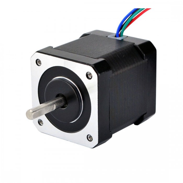
Work out the approximate back emf due to rotation. From the formula given earlier, this is sqrt(2) * pi * rated_holding_torque * revs_per_second / rated_current. My motors have rated current of 1.68A and holding torque of 0.44Nm, so the result is 1.414 * 3.142 * 0.44 * 8.7/1.68 = 10.1V.
Preferably, the driver supply voltage should be at least the sum of these two back emfs, plus a few more volts. If you have two motors in series then the required voltage is doubled.
In my example, this gives 32.5V, which is above the 25V recommended input voltage for the Duet 2. But at least we know that for a worst-case delta move with 200mm/sec travel speed, if I use a 24v stepper motor supply then that is more than 2/3 of the theoretical value, so the torque available for that move should not drop off by more than about 1/3 of the usual torque available. On the other hand, a 12V supply would clearly be inadequate - which explains why I was only able to achieve 150mm/sec before I upgraded the printer to 24V.
Source from:
https://blog.oyostepper.com/2018/04/25/how-to-work-out-the-stepper-motor-power-supply-voltage/


No comments:
Post a Comment