Wednesday, October 30, 2019

NEMA 34 Size Motor Applications and Dimensions

NEMA 34 is a high torque hybrid bipolar stepping motor with a 3.4×3.4 inch faceplate. Hybrid stepper has the combination of the features of the Variable Reluctance Stepper Motor and Permanent Magnet Stepper Motor. This motor has a step angle of 1.8 deg., this means that it has 200 steps per revolution and for every step it will cover 1.8°.  This NEMA 34 is a 2-Phase motor with 4 wires. Compatible controllers for this motor are CW230, CW250 and CW860.


How to use NEMA 34 Stepper Motor
As mentioned above this stepper motor draws high current so instead of controlling it directly, use an appropriately powerful stepper motor drivers like cw230. Wiring diagram for NEMA 34 Stepper motor is given below:
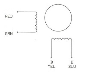
 How to use NEMA 34 Stepper Motor

As shown in wiring diagram there are four wires of different colours i.e. Red, Green, Yellow and Blue. These wires are connected to two different coils. Red and Green connected to one coil while Yellow and Blue are connected to other.

To rotate the motor coils are energized in a logical sequence. To rotate the motor in anticlockwise motion of the rotor the phases are energized in the following sequence +A, +B, -A, -B, +B, +A and for the clockwise rotation, the sequence is +A, -B, +B, +A……..


Stepper Motor Applications
CNC machines
Precise control machines
3D printer/prototyping machines (e.g. RepRap)
Laser cutters
Pick and place machines


NEMA 34 Stepper Motor Dimensions
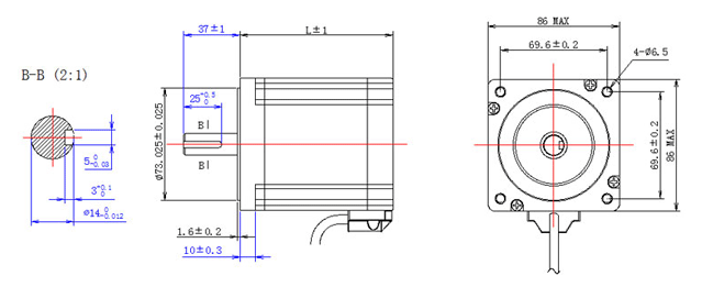
NEMA 34 Stepper Motor Dimensions

See more:

https://www.oyostepper.com/article-1091--NEMA-34-Stepper-Motor-Applications-and-Dimensions.html

Tuesday, October 22, 2019

Stepper Motor Heating And Power Supply Voltage


There are two major causes of hybrid stepper motor heating: copper losses and iron losses. Copper losses are the easiest to understand; this is the heat generated by current passing through a resistance, as in the current passing through the motor’s winding resistance. Often this is referred to as “I2R” dissipation.

This cause of motor heating is at a maximum when the motor is stopped and rapidly diminishes as the motor speeds up since the inductive current is inversely proportional to speed.

Stepper Motor Heating And Power Supply Voltage

Eddy current and hysteresis heating are collectively called iron losses. The former induces currents in the iron of the motor while the latter is caused by the re-alignment of the magnetic domains in the iron. You can think of this as “friction heating” as the magnetic dipoles in the iron switch back and forth. Either way, both cause the bulk heating of the motor. Iron losses are a function of AC current and therefore the power supply voltage.

As shown earlier, motor output power is proportional to power supply voltage, doubling the voltage doubles the output power. However, iron losses outpace motor power by increasing non-linearly with increasing power supply voltage. Eventually the point is reached where the iron losses are so great that the motor cannot dissipate the heat generated. In a way this is nature’s way of keeping someone from getting 500HP from a NEMA 23 motor by using a 10kV power supply.

At this point it is important to introduce the concept of overdrive ration. This is the ration between the power supply voltage and the motor’s rated voltage. An empirically derived maximum is 25:1, meaning the power supply voltage should never exceed 25 times the motor’s rated voltage or 32 times the square root of motor inductance.

Check here more “steppermotor for sale”.

Thursday, December 13, 2018

What is pole count of stepping motor?

Simply defined, a pole is a north or south magnetic field of force that is generated by a permanent magnet or current passing through a coil of wire. For stepper motors, however, this definition does not necessarily translate to a simple definition of pole count. Different manufacturers use different names to refer to their poles and various stepper-motor types have varying kinds and numbers of poles.

The motor drive energizes stator teeth one after the other to make the rotor turn, thanks to its magnets’ tendency to force alignment with the stator teeth.

Permanent-magnet stepper motors online are the simplest. Manufacturers define their pole count by the number of pole pairs or stator windings. Increasing the number of pole pairs on the rotor itself (or adding more stator phases) increases resolution. Most permanent-magnet steppers have a resolution of 30° to 3° per step.

Variable-reluctance and hybrid stepper motors have teeth on their rotors, and stators define pole count. These types of stepper motors move 1.8° or less per step.

• For variable reluctance, the more teeth, the greater pole count, the greater the resolution. Rotation step angle is half that of a permanent-magnet stepper motor with the same number of stator windings.

• In contrast, hybrid stepper motors have rotors covered by two radial sections (cups) of magnetized teeth, with a gap in between them. The two cups have teeth that are offset by one tooth in relation to the other. Here too, the greater number of teeth, the greater number of poles, the higher the resolution and the smaller the steps. This means it can rotate a very small amount (See FAQ: What are hybrid stepper motors?) because of its pole count.

This can influence design decisions in a few ways. Basically, the more poles, the more precisely a drive can control stepper motor output. Beyond this simple fact, manufacturers offer varying arrangements and numbers of stator poles and teeth. Designers must consider the application’s required precision, pole and teeth count, design speed, torque, acceleration, and other parameters. Because pole count affects torque as well, it can lead to design decisions related to inertia matching as well (For more on inertia matching, see FAQ: How do stepper motors handle inertia mismatch?) One last note: because the angle of step affects motor vibration and noise, designers should keep that motor feature in mind when making decisions about pole count.

Tuesday, December 11, 2018

How to Control a Stepper Motor with Your Muscles

Background
Designed and written by José Enrique López Pérez, student of Electronic Engineering in Oaxaca, Mexico.

Where can we find a stepper motor? Instead of buying one, you can also get a stepper motor by opening up an old printer. These motors are generally used in devices controlled by digital systems, like robotics, automation, and, of course, our favorite, 3D printers!

How to Control a Stepper Motor with Your Muscles


What are advantages of Stepper motors?() The axis of a stepper motor rotates at regular intervals instead of doing it continuously like DC (direct current) motors. A Stepper Motor is programmed by a micro controller and can be used for precise positioning within a wide range of applications. Precise positioning of a DC motor is not possible by simple methods.

How does a stepping motor work? The stepper motor is known for its ability to convert a train of input pulses (typically square wave pulses) applied to its coils, into a precisely defined increment of movement in the shaft's position. Each pulse moves the shaft through a fixed angle. This is called a step, hence the name stepper motor. The result of this movement is fixed and repeatable, allowing accurate and reliable positioning.

Why are there so many cables in a Stepper Motor? Unipolar Stepper motors can have 5, 6 or 8 terminals that connect to magnetic coils that allow precise positioning, in addition to other cables such as power and ground.

Circuit of Stepper Motor

How to Control a Stepper Motor with Your Muscles


How is a Stepper Motor different from a DC Motor?

A DC (direct current) motor moves continuously, without steps. It´s used when its important to continually regulate the velocity of a motor. These are the common motors you find in radiocontrol cars and other toys.

A DC motor has two terminals, (+) and (-). Electric current is generated through this terminals making the motor spin in a determinate direction.

How to Control a Stepper Motor with Your Muscles


What are the acceleration requirements of step motor?


Wednesday, December 5, 2018

What is the diagram of a stepping motor?

A best stepper Motor for sale is basically a synchronous Motor. In stepper motor there is no brushes. This motor does not rotate continuously, instead it rotates in form of pluses or in discrete steps. Thats why it is called stepper motor.
The principle of Working of stepper motor is Electro-Magnetism.
The Stepper Motor is of following types:
  • Permanent Magnet
  • Variable Reluctance
  • Hybrid Stepper Motor
1.Permanent Magnet Stepper motor
2.Variable Reluctance Stepper motor
3.Hybrid Stepper Motor

Friday, November 30, 2018

High Responsiveness and Excellent Synchronization of Stepper Motor

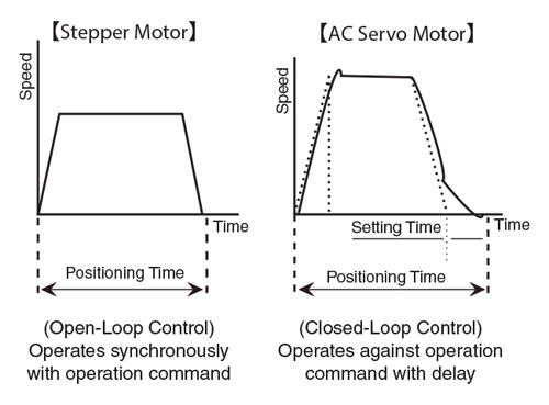
The third remarkable feature of stepper motors best is responsiveness. The open-loop control, which sends one-way commands to the motor, has a high followup mechanism toward commands. While servo motors, which wait for feedback from the encoder, tend to have "delays" with commands, stepper motors operate synchronously with a pulse. Therefore, there are very few "delays," resulting in excellent response. For this reason, stepper motors are suitable for applications that require synchronous operations of multiple motors. One example is a board transferring application that requires two conveyors, with one motor mounted respectively, to transfer boards in between the two conveyors.

Point 2
Excellent Low / Mid-Speed Range!
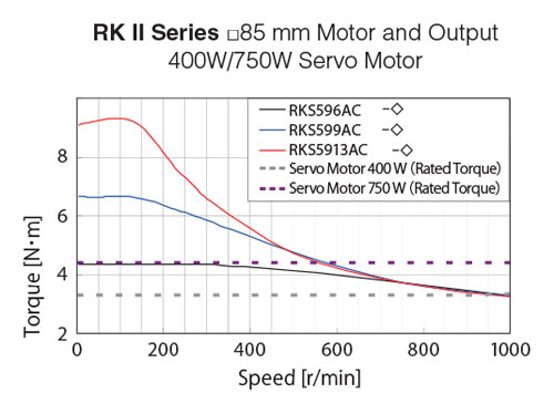
Example: Torque of a motor frame size 85 mm is equivalent to a rated torque of a 400 W servo motor when 1000 r/min.

Torque in an even lower speed range can be up to 5 times higher. For a shortdistance positioning, having high torque in the low / mid-speed range is essential.
RKII Torque Chart
Stepper Motor Open Loop vs Servo Closed Loop

Wednesday, November 28, 2018

Driving a unipolar stepper motor with the NXP PCA9537

The NXP PCA9537 is a 10-pin CMOS totem pole GPIO with an SMBus and I2C two-wire bus so it can interface to most microcontrollers (Figure 3).


Figure 3: The NXP PCA9537 is a totem pole GPIO that takes the I2C byte sequences from the host controller and provides the requisite waveforms to the gate inputs G1 through G4. (Image source: NXP)

In the diagram, the motor is a 12-V unipolar nema 23 stepper motor with a current rating of 1.25 A. For users that want to modify the diagram and tweak it to their own application, there is a fully interactive schematic of the unipolar driver available on Schematics.com.

The PCA9537 has a 4-bit configuration register, 4-bit input port register, and a 4-bit output port register, and a 4-bit polarity inversion register for “active high” or “active low” operation. The GPIO has a fixed I2C-bus slave address of 92H and it takes the I2C byte sequences from the host controller and provides the requisite waveforms to the gate inputs G1 through G4.

The diagram also shows the NXP PCA9665, an IC that serves as an interface between most standard parallel-bus microcontrollers/microprocessors and the serial I2C-bus allowing the parallel bus system to communicate bidirectional with the I2C-bus. The type of waveform will be one corresponding to wave, two-phase or half-step drive, as chosen by the user. The duration of the pulses is controlled by time delay implemented in the host controller firmware. It is shown as a reference for the various waveforms. The maximum I2C-bus speed supported by PCA9537 is 400 kHz.

To drive the stepper motor best price at approximately 18 RPM, use the following byte sequence, where ‘S’ stands for I2C-bus START condition, and ‘P’ stands for STOP condition. Also, DLY1 and DLY2 are time delays implemented by the microcontroller firmware. Numbers are represented in hexadecimal notation:

S, 0x92, 0x03, 0x00, P // Set all 4 IO pins of PCA9537 as OUTPUT pins;
// IO Configuration Register = 0x00
Set DLY1 = 300 ms // Time delay between steps; 18 RPM for a 7.5˚ motor

//Start of waveform loop
S, 0x92, 0x01, 0x08, P // Start the half-step sequence waveform
Execute time delay between steps = DLY1
S, 0x92, 0x01, 0x0C, P // outputs for the next step
Execute time delay between steps = DLY1
S, 0x92, 0x01, 0x04, P // outputs for the next step
Execute time delay between steps = DLY1
S, 0x92, 0x01, 0x06, P // outputs for the next step
Execute time delay between steps = DLY1
S, 0x92, 0x01, 0x02, P // outputs for the next step
Execute time delay between steps = DLY1
S, 0x92, 0x01, 0x03, P // outputs for the next step
Execute time delay between steps = DLY1
S, 0x92, 0x01, 0x01, P // outputs for the next step
Execute time delay between steps = DLY1
S, 0x92, 0x01, 0x09, P // outputs for the next step
Execute time delay between steps = DLY1
// Loop through waveform sequence to keep running motor
// OR execute next two steps if desired
Execute time delay = DLY2 // Hold in current position for time = DLY2
S, 0x92, 0x01, 0x00, P // Turn off motor

(Byte sequence source: NXP)
Of course, some users may want to drive multiple motors. For this, many single-chip options are also available. In the meantime, it’s good to practice on the PCA9537 and the unipolar, single-motor, interactive schematic shown here.

How to enhance the control capability of linear guide rails?

1.Brief of linear guide rail A linear guide rail is a mechanical component used in linear motion systems to guide and support a moving carr...