The schematic is complete. For most motors, the diodes can be usual rectifier types rated at 1A (i.e. 1N4004). Fast rectifier types are usually a better choice. If you're using N-FETs with included protection diodes, there is no need for external diodes. Also, with FET transistors, the gate can be connected directly to Arduino pin, without 1k resistors. Those resistors are required if you use bipolar transistors instead of FETs. Yes, you can use NPN transistors. Darlington transistors are recommended. Just make sure the transistor can handle load current (drain-source current, collector-emitter current) and it can be fully switched on by Arduino (gate threshold voltage, DC gain).
The resistor connected between OUT and ADJ pins of LM317 step driver controls the constant current. For 2.4 ohms, the current is 1.25/2.4 = 0.5A. Use a correct wattage resistor (2-3W). Replace the resistor with a suitable value for the motor rated current. The voltage at LM317 input cannot exceed 35V.

void halfDrive(unsigned int numSteps, unsigned int stepDelay = 5) {
for (unsigned int i = 0; i < numSteps; i++) {
PORTB = B00000001;
delay(stepDelay);
PORTB = B00000011;
delay(stepDelay);
PORTB = B00000010;
delay(stepDelay);
PORTB = B00000110;
delay(stepDelay);
PORTB = B00000100;
delay(stepDelay);
PORTB = B00001100;
delay(stepDelay);
PORTB = B00001000;
delay(stepDelay);
PORTB = B00001001;
delay(stepDelay);
}
}
The third way is called full drive. Two adjacent coils are on at the same time, resulting in highest torque possible.

void fullDrive(unsigned int numSteps, unsigned int stepDelay = 5) {
for (unsigned int i = 0; i < numSteps; i++) {
PORTB = B00000011;
delay(stepDelay);
PORTB = B00000110;
delay(stepDelay);
PORTB = B00001100;
delay(stepDelay);
PORTB = B00001001;
delay(stepDelay);
}
}
These are basic and lightweight functions for driving a stepper. The numSteps argument is a multiple of 4 steps. That is, for numSteps=1, the motor will make 4 steps. For the common 1.8 degree stepper motor, 200 steps/turn motors, set numSteps to 50 to make a full rotation. These functions do not support changing direction.
The resistor connected between OUT and ADJ pins of LM317 step driver controls the constant current. For 2.4 ohms, the current is 1.25/2.4 = 0.5A. Use a correct wattage resistor (2-3W). Replace the resistor with a suitable value for the motor rated current. The voltage at LM317 input cannot exceed 35V.

All it needs now is the software. Rotating a stepper is very simple, that's why I wrote my own code instead of using a library. To simplify the code I didn't use standard digitalWrite routines. I wrote directly to the port. First the port must be set as output in setup() with DDRB = 0x3F;. This sets digital pins 8 to 11 as outputs. Check Arduino Port Manipulation page.
The coils must be energized in a specific order: a half of one coil (A), then a half of the other (B). Pulses should then energize the remaining coil halves (C half of the first coil, then D half of the other coil). The order determines direction. Just remember: you should not energize in a sequence one half of a coil, then the other half of the same coil. The motor will make a step in one direction and one step backwards. It doesn't harm the motor though. A-B-C-D and A-D-C-B are valid sequences, but A-C-B-D is not.
Because you can power 4 coils, there are actually 3 ways of doing it. You can use wave drive. Each of the 4 coils is powered sequentially so that only one coil is powered an any time. This results in less power consumption and less torque. Below is the pulse train and the code used to generate it.
void waveDrive(unsigned int numSteps, unsigned int stepDelay = 5) {
for (unsigned int i = 0; i < numSteps; i++) {
PORTB = B00000001;
delay(stepDelay);
PORTB = B00000010;
delay(stepDelay);
PORTB = B00000100;
delay(stepDelay);
PORTB = B00001000;
delay(stepDelay);
}
}
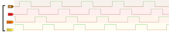
The motor can be rotated in half drive mode too. In this mode a pulse is kept high when the next starts. Half of the time, two adjacent coils are energized, resulting in higher torque. When both adjacent coils are on, the axis turns one half of the step, resulting in a smoother rotation. With the same delay, pulse width increases, meaning you can use lower step delays.
void halfDrive(unsigned int numSteps, unsigned int stepDelay = 5) {
for (unsigned int i = 0; i < numSteps; i++) {
PORTB = B00000001;
delay(stepDelay);
PORTB = B00000011;
delay(stepDelay);
PORTB = B00000010;
delay(stepDelay);
PORTB = B00000110;
delay(stepDelay);
PORTB = B00000100;
delay(stepDelay);
PORTB = B00001100;
delay(stepDelay);
PORTB = B00001000;
delay(stepDelay);
PORTB = B00001001;
delay(stepDelay);
}
}
The third way is called full drive. Two adjacent coils are on at the same time, resulting in highest torque possible.
void fullDrive(unsigned int numSteps, unsigned int stepDelay = 5) {
for (unsigned int i = 0; i < numSteps; i++) {
PORTB = B00000011;
delay(stepDelay);
PORTB = B00000110;
delay(stepDelay);
PORTB = B00001100;
delay(stepDelay);
PORTB = B00001001;
delay(stepDelay);
}
}
These are basic and lightweight functions for driving a stepper. The numSteps argument is a multiple of 4 steps. That is, for numSteps=1, the motor will make 4 steps. For the common 1.8 degree stepper motor, 200 steps/turn motors, set numSteps to 50 to make a full rotation. These functions do not support changing direction.


No comments:
Post a Comment